(Fig. 7.2-1)
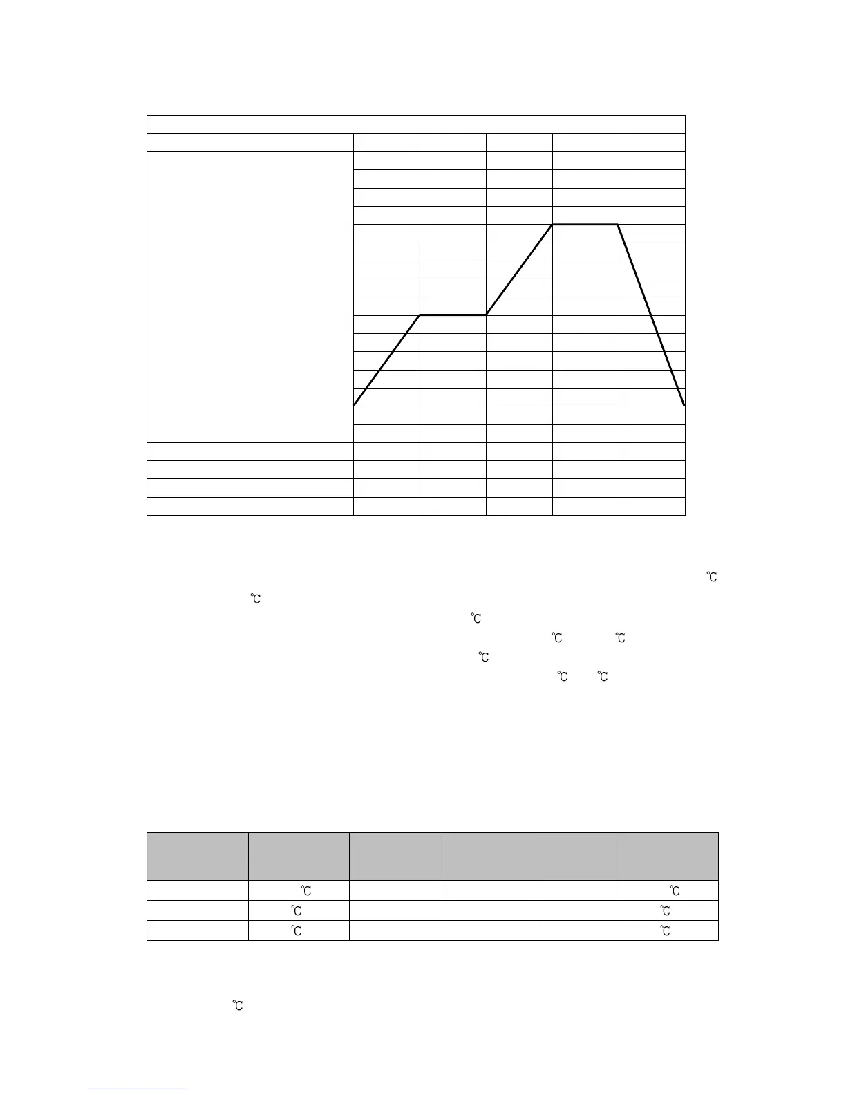
Explanation of Program Pattern
Step 1: After program control starts, control is performed so that SV gradually rises from 0
to 500 for 30 minutes.
Step 2: Control is performed to keep the SV at 500 for 1 hour.
Step 3: Control is performed so that SV gradually rises from 500 to 1000 for 40 minutes.
Step 4: Control is performed to keep the SV at 1000 for 1 hour.
Step 5: Control is performed so that SV gradually falls from 1000 to 0 for 2 hours.
• Example of PID Block Setting
If program pattern is not set for a step, its PID block number becomes 1 (factory default).
We highly recommend that you leave the factory defaults of PID block 1 as they are, and
set the values from Block 2.
Control parameters such as PID, ARW are common to all patterns.
Block
number
proportional
band
1 10 200 sec 50 sec 50% 10
2 10 (*) 200 sec (*) 50 sec (*) 50% (*) 10 (*)
3 10 (*) 200 sec (*) 50 sec (*) 50% (*) 10 (*)
(*) Setting items in PID block are determined after performing AT. So they are currently factory default values.
• Example of Wait Value Setting
Wait value: 10
Wait value is common to all steps of each pattern.
0
500
1000