- 155 -
14. Making Program Pattern Table and Data Table
Before setting program, make a program pattern table and data table.
14.1 Making Program Pattern Table
Please make a copy of the program pattern table (p.157), and follow the procedure below.
(1) Write a step SV, step time, PID block number, Wait function Enabled/Disabled for
each step from Step 1 in numerical order.
(Even if the same block number is used, write for every step.)
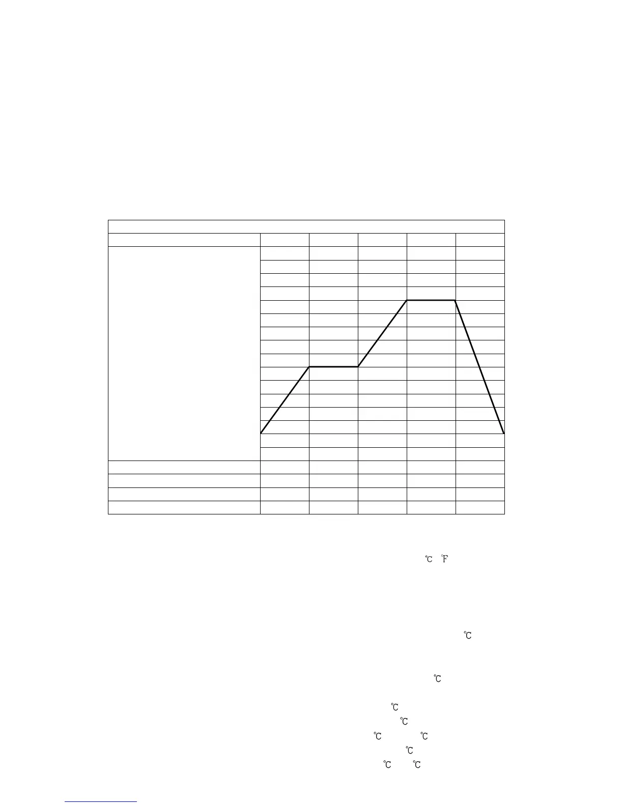
(2) Draw a line graph of step SV.
Program Pattern Table
(Fig. 14.1-1)
Explanation of Program Pattern Table
Program pattern table consists of Y axis which represents the step SV ( , ), and X axis which
represents the step time (Hours : Minutes, Minutes : Seconds).
Step SV is considered to be the SV at the end of the step.
Step time is considered to be the step process time.
• The relation between the step SV and step time can be explained as follows.
Step 1: The control is performed so that the temperature reaches from 0 to 500 for 30 minutes.
Depending on the selection in [Program control start type], control is performed as follows.
• When SV start is selected: Performs control from the step SV set in [Step SV when
program control starts] so that the temperature reaches 500 .
• When PV start or PVR start is selected: Step SV and time are advanced to PV, and
control starts so that the temperature reaches 500 .
Step 2: The control is performed so that SV is maintained at 500 for 1 hour.
Step 3: The control is performed so that SV rises from 500 to 1000 for 40 minutes.
Step 4: The control is performed so that SV is maintained at 1000 for 1 hour.
Step 5: The control is performed so that SV drops from 1000 to 0 for 2 hours.
0
500
1000