- 48 -
8.2 Setting Items in Event Setting Mode
Setting items in Event Setting Mode differs depending on the selection in [Event output EV allocation].
If 001 (High limit alarm) to 012 (High/Low limits alarm with standby independent alarm) are selected in
[Event output EV allocation], EV alarm value will be set.
If 015 (Time signal output) is selected in [Event output EV allocation], TS output OFF time and TS
output ON time can be set.
Settings are performed for the pattern number selected when entering Event setting mode.
Setting values are common to all steps in each pattern.
During program control RUN, only the performing pattern can be set.
If ‘Pattern link Enabled’ is selected in [Pattern link]: Even if the performing pattern is changed from 1 to 2
during Event setting mode, Pattern 1 will be remained, and pattern number will not be updated until the
unit reverts to the RUN mode.
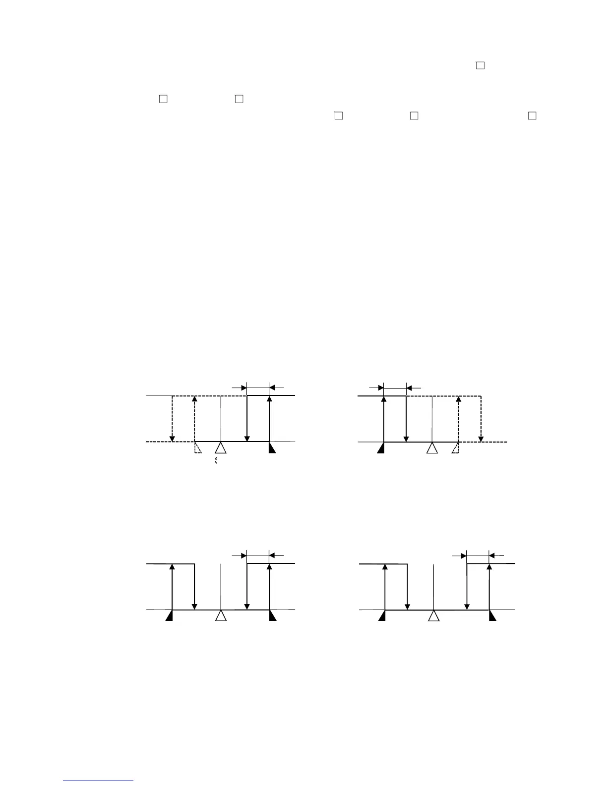
• About alarm output
EV1 alarm output actions are shown below.
EV1 alarm output will be substituted by EV2 or EV3 alarm output.
• High limit alarm • Low limit alarm
(Fig. 8.2-1) (Fig. 8.2-2)
• High/Low limits alarm • High/Low limits independent alarm
(Fig. 8.2-3) (Fig. 8.2-4)