- 143 -
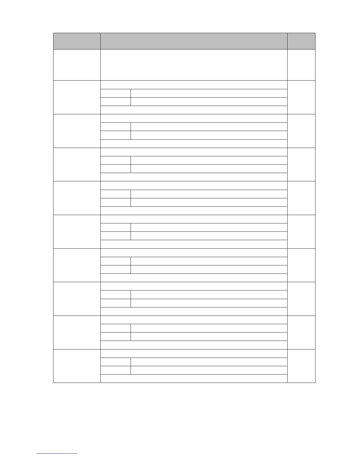
13.5 Wait Parameter Setting Mode
Characters,
Factory Default
Setting Item, Setting Range Data
wait
1 ///0
Wait value
Setting range: 0 to 20% of input span (*)
(*) DC voltage, current inputs: 0 to 20% of scaling span (The placement
of the decimal point follows the selection.)
wact
1 ----
PTN/STEP
indicator 1 lights up.
Step 1 wait function Enabled/Disabled
---- Disabled
use/ Enabled
Not available if Wait value is set to 0 or 0.0.
wact
1 ----
PTN/STEP
indicator 2 lights up.
Step 2 wait function Enabled/Disabled
---- Disabled
use/ Enabled
Not available if Wait value is set to 0 or 0.0.
wact
1 ----
PTN/STEP
indicator 3 lights up.
Step 3 wait function Enabled/Disabled
---- Disabled
use/ Enabled
Not available if Wait value is set to 0 or 0.0.
wact
1 ----
PTN/STEP
indicator 4 lights up.
Step 4 wait function Enabled/Disabled
---- Disabled
use/ Enabled
Not available if Wait value is set to 0 or 0.0.
wact
1 ----
PTN/STEP
indicator 5 lights up.
Step 5 wait function Enabled/Disabled
---- Disabled
use/ Enabled
Not available if Wait value is set to 0 or 0.0.
wact
1 ----
PTN/STEP
indicator 6 lights up.
Step 6 wait function Enabled/Disabled
---- Disabled
use/ Enabled
Not available if Wait value is set to 0 or 0.0.
wact
1 ----
PTN/STEP
indicator 7 lights up.
Step 7 wait function Enabled/Disabled
---- Disabled
use/ Enabled
Not available if Wait value is set to 0 or 0.0.
wact
1 ----
PTN/STEP
indicator 8 lights up.
Step 8 wait function Enabled/Disabled
---- Disabled
use/ Enabled
Not available if Wait value is set to 0 or 0.0.
wact
1 ----
PTN/STEP
indicator 9 lights up.
Step 9 wait function Enabled/Disabled
---- Disabled
use/ Enabled
Not available if Wait value is set to 0 or 0.0.