- 142 -
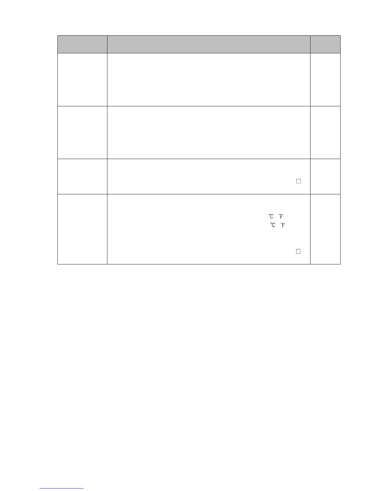
Characters,
Factory Default
Setting Item, Setting Range Data
h1//
/ //0.0
h1// and CT1
current value are
alternately
indicated.
Heater burnout alarm 1 value
Setting range:
20 A: 0.0 to 20.0 A
100 A: 0.0 to 100.0 A
Available when C5W, EIW, W option is ordered, and OUT1 is relay contact output
or non-contact voltage output type.
h2//
/ //0.0
h2// and CT2
current value are
alternately
indicated.
Heater burnout alarm 2 value
Setting range:
20 A: 0.0 to 20.0 A
100 A: 0.0 to 100.0 A
Available when C5W, EIW, W option is ordered, and OUT1 is relay contact output
or non-contact voltage output type.
lp_t
/ ///0
Loop break alarm time
Setting range: 0 to 200 minutes
Available when /014 (Loop break alarm output) is selected in [Event output EV
allocation].
lp_h
/ ///0
Loop break alarm span
Setting range:
Thermocouple, RTD input without decimal point: 0 to 150 ( )
Thermocouple, RTD input with decimal point: 0.0 to 150.0 ( )
DC voltage, current inputs: 0 to 1500 (The placement of the decimal
point follows the selection.)
Available when /014 (Loop break alarm output) is selected in [Event output EV
allocation].