- 7 -
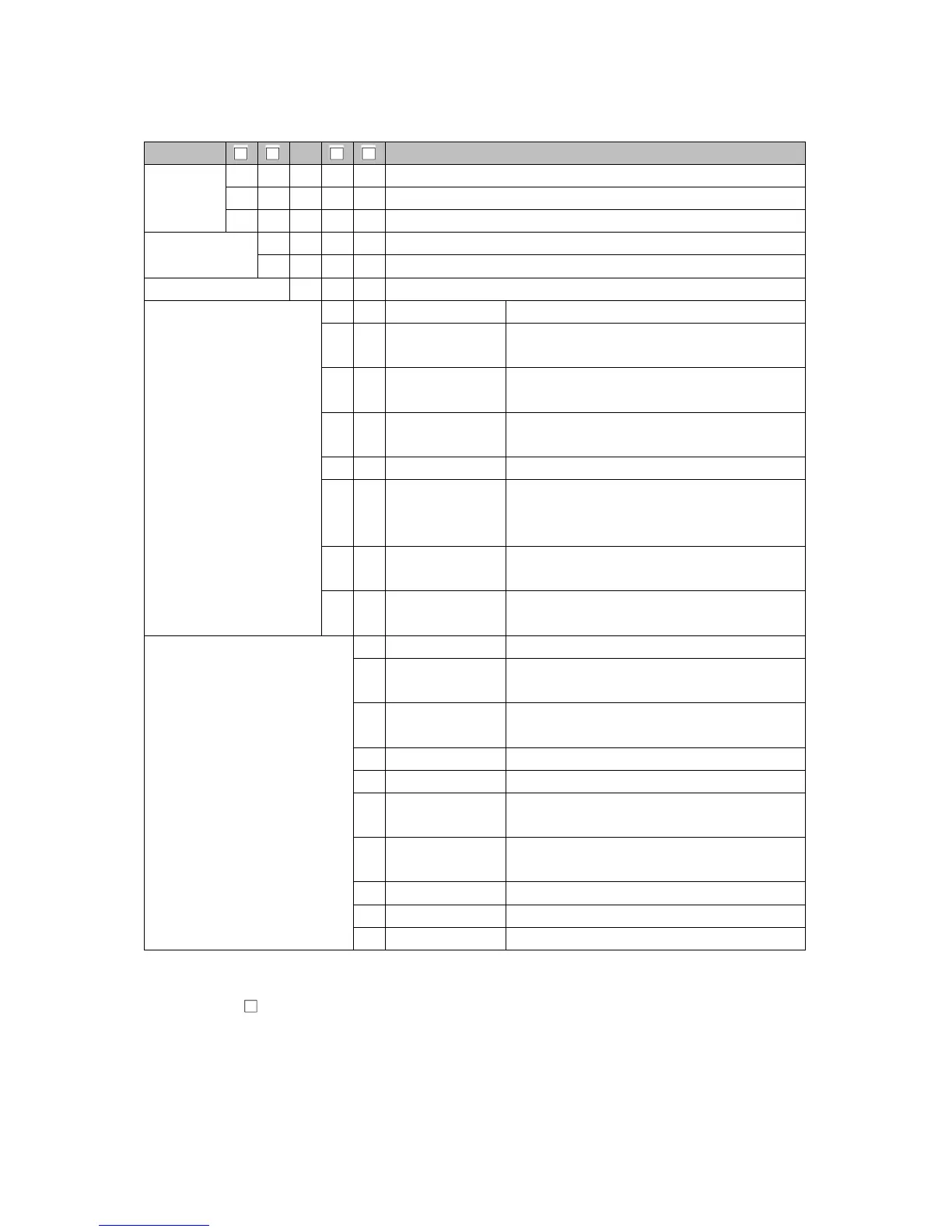
1. Model
1.1 Model
PCB1 0-
Control
output
OUT1
R Relay contact output
S Non-contact voltage output
A Direct current output
Power supply
voltage
0 100 to 240 V AC
1 24 V AC/DC
Input 0 Multi-range
Option 1
0 Option 1 not needed.
1 EV2(DR) (*1)
Event output EV2, or Heating/Cooling
control output OUT2 Relay contact output
2 DS
Heating/Cooling control output OUT2
Non-contact voltage output
3 DA
Heating/Cooling control output OUT2
Direct current output
4 P24 Insulated power output
5
EV3(DR)
(*1), (*2)
Event output EV3 + Event output EV2, or
Heating/Cooling control output OUT2
Relay contact output
6 EV3DS (*2)
Event output EV3 + Heating/Cooling control
output OUT2 Non-contact voltage output
7 EV3DA (*2)
Event output EV3 + Heating/Cooling control
output OUT2 Direct current output
Option 2
0 Option 2 not needed.
1 C5W(20A) (*3)
Serial communication
+ Heater burnout
alarm output + Event input (*4)
2 C5W(100A) (*3)
Serial communication
+ Heater burnout
alarm output + Event input (*4)
3 EIW(20A) (*3) Event input + Heater burnout alarm output
4 EIW(100A) (*3) Event input + Heater burnout alarm output
5 EIT (*2)
Event input + Transmission output (4 – 20
mA DC)
6 C5
Serial communication
RS-485 + Event
input (*4)
7 W(20A) (*3) Heater burnout alarm output
8 W(100A) (*3) Heater burnout alarm output
9 EI Event input + Event output EV3
(*1) When ‘Heating/Cooling control Relay contact output’ is selected in [Event output EV2 allocation],
it works as the DR option.
(*2) The EV3D option and EIT option cannot be ordered together.
(*3) When control output OUT1 is Relay contact output or Non-contact voltage output,
the C5W, EIW or W option can be ordered.
(*4) ‘SV digital transmission’ or ‘SV digital reception’ can be selected in [Communication protocol].