- 9 -
2. Name and Functions of Controller
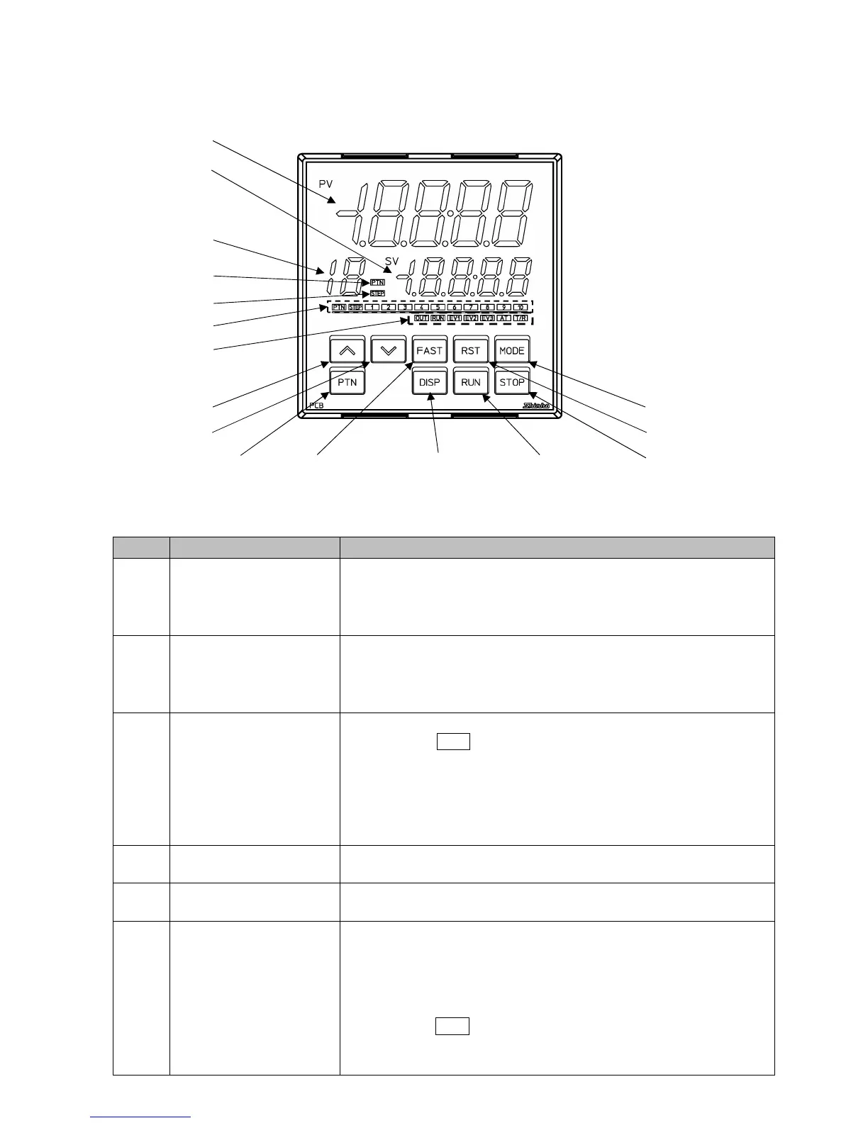
(Fig. 2-1)
Display, Indicator
No. Name Description
①
PV Display
(Red)
Indicates process variable (PV) in RUN mode.
Indicates setting characters in Setting mode.
Flashes during Wait action or Program control Hold in program
control.
②
SV Display
(Green)
Indicates the desired value (SV), Output manipulated variable (MV),
or Remaining time (TIME) in RUN mode.
Retains display indication at power OFF.
Indicates the set values in setting mode.
③
PTN/STEP Display
(Orange)
Indicates the pattern number or step number.
Each time the DISP key is pressed, the PTN/STEP Display (③),
and the PTN/STEP indicator (⑥) alternately indicate the pattern
number and step number.
Flashes during Wait action or when the step number is indicated.
If ‘SV digital reception’ is selected in [Communication protocol],
r is indicated.
④
PTN indicator
(Orange)
Lights up when the pattern number is indicated on the PTN/STEP
Display.
⑤
STEP indicator
(Orange)
Lights up when the step number is indicated on the PTN/STEP
Display.
⑥
PTN/STEP indicator
(Green)
LED for the pattern number or step number lights up.
If the PTN/STEP Display (③) indicates the pattern number, the
PTN/STEP indicator (⑥) lights up its step number. If the PTN/STEP
Display indicates the step number, the PTN/STEP indicator lights
up its pattern number.
Each time the DISP key is pressed, the PTN/STEP indicator and the
PTN/STEP Display alternately indicate the pattern number and step
number.
①
②
⑦
⑧
⑨ ⑮
⑯
③
④
⑤
⑥
⑫⑩ ⑬ ⑭⑪