- 22 -
(2) SV digital transmission
If ‘SV digital transmission’ is selected in [Communication protocol]:
Step SV can be digitally transmitted to the connected Shinko indicating controllers with the SV
digital transmission (C5 option) function.
If ‘SV digital reception’ is selected in [Communication protocol]:
Receives digital SV via SVTC command from the connected Shinko programmable controllers.
Shinko programmable controllers:
PC-900, PCD-33A [When the SVTC (SV digital transmission) option is ordered]
PCA1, PCB1 (When ‘SV digital transmission’ is selected in [Communication protocol])
Update cycle: 250 ms
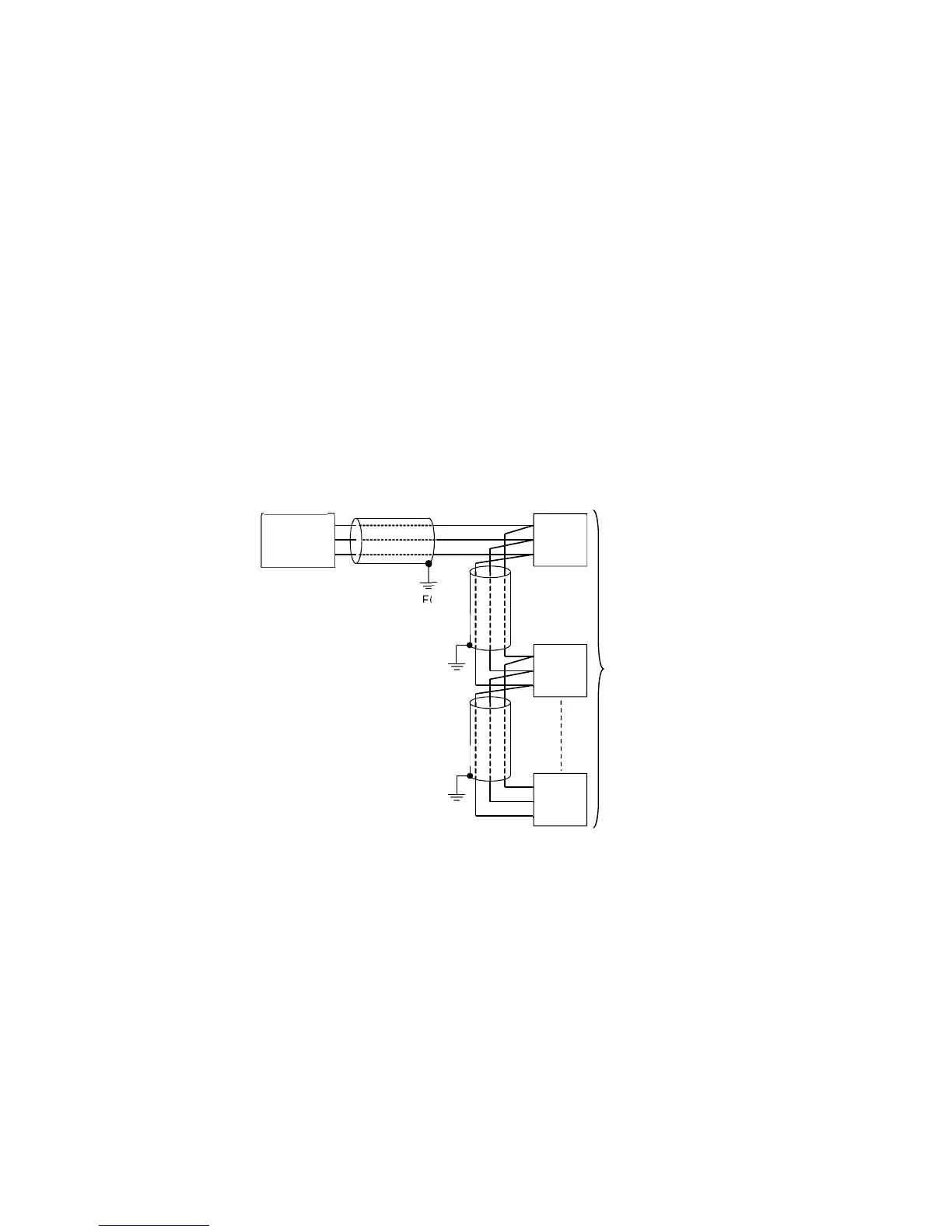
Wiring
For the PCB1 and controllers with the communication function, connect YA (-) to YA (-), YB (+)
to YB (+), SG to SG terminal respectively.
Up to 31 units can be connected.
Wiring example of PCB1 and controllers with communication function
(Fig. 4.4.6-3)
Shield wire
Connect only one end of the shield to the FG terminal to avoid a ground loop. If both ends of the shield
wire are connected to the FG terminal, the circuit will be closed, resulting in a ground loop. This may
cause noise.
Be sure to ground the FG terminal.
Recommended cable: OTSC-VB 2PX0.5SQ (made by Onamba Co., Ltd.) or equivalent (Use a twisted
pair cable.)
FG
FG
FG
YA(-) ⑩
YB(+) ⑪
SG ⑫
Shield
wire
Shield wire
Shield wire
PCB1
Controllers with
communication
function
(Max. 31 units)
YA(-)
YB(+)
SG
YA(-)
YB(+)
SG
YA(-)
YB(+)
SG