- 4 -
2. Wiring Precautions
Caution
• Do not leave wire remnants in the instrument, as they could cause a fire or malfunction.
• Use the solderless terminal with an insulation sleeve in which the M3 screw fits when wiring the
instrument.
• The terminal block of this instrument is designed to be wired from the left side. The lead wire must be
inserted from the left side of the terminal, and fastened with the terminal screw.
• Tighten the terminal screw using the specified torque. If excessive force is applied to the screw when
tightening, the terminal screw or case may be damaged.
• Do not pull or bend the lead wire on the terminal side when wiring or after wiring, as it could cause
malfunction.
• This instrument does not have a built-in power switch, circuit breaker and fuse. It is necessary to install
a power switch, circuit breaker and fuse near the controller.
(Recommended fuse: Time-lag fuse, rated voltage 250 V AC, rated current 2 A)
• For a 24 V AC/DC power source, do not confuse polarity when using direct current (DC).
• Do not apply a commercial power source to the sensor which is connected to the input terminal nor
allow the power source to come into contact with the sensor.
• Use a thermocouple and compensating lead wire according to the sensor input specifications of this
controller.
• Use the 3-wire RTD according to the sensor input specifications of this controller.
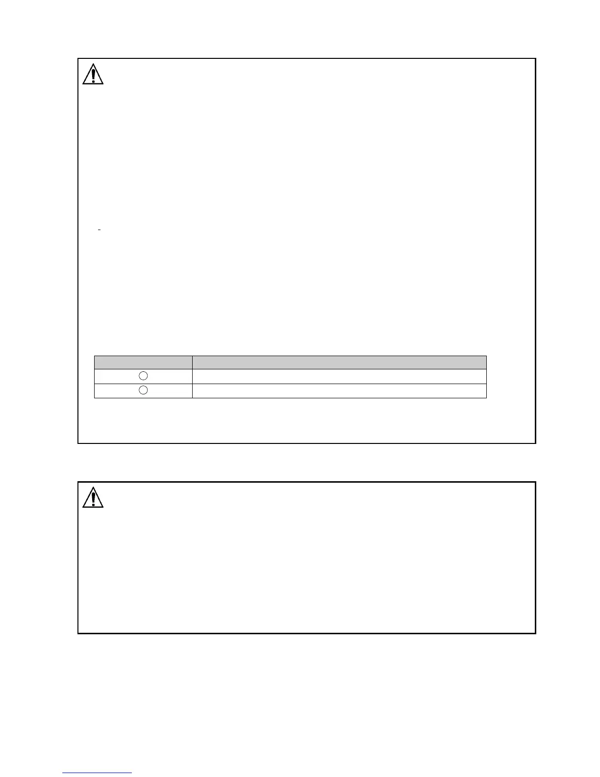
• For DC voltage input, (+) side input terminal number of 0 to 5 V DC, 1 to 5 V DC, 0 to 10 V DC differs
from that of 0 to 1 V DC.
Terminal Number DC Voltage Input
21
(+) side of 0 to 5 V DC, 1 to 5 V DC, 0 to 10 V DC
22
(+) side of 0 to 1 V DC
• When using a relay contact output type, externally use a relay according to the capacity of the load to
protect the built-in relay contact.
• When wiring, keep input wires (thermocouple, RTD, etc.) away from AC power sources or load wires.
3. Operation and Maintenance Precautions
Caution
• It is recommended that AT be performed on the trial run.
• Do not touch live terminals. This may cause electrical shock or problems in operation.
• Turn the power supply to the instrument OFF before retightening the terminal or cleaning.
Working on or touching the terminal with the power switched ON may result in severe injury or death
due to electrical shock.
• Use a soft, dry cloth when cleaning the instrument.
(Alcohol based substances may tarnish or deface the unit.)
• As the display section is vulnerable, be careful not to put pressure on, scratch or strike it with a hard
object.