6
A2 value
PV SV
Value
• Set the value with the or key.
• Not available if
is selected
during A2 type selection
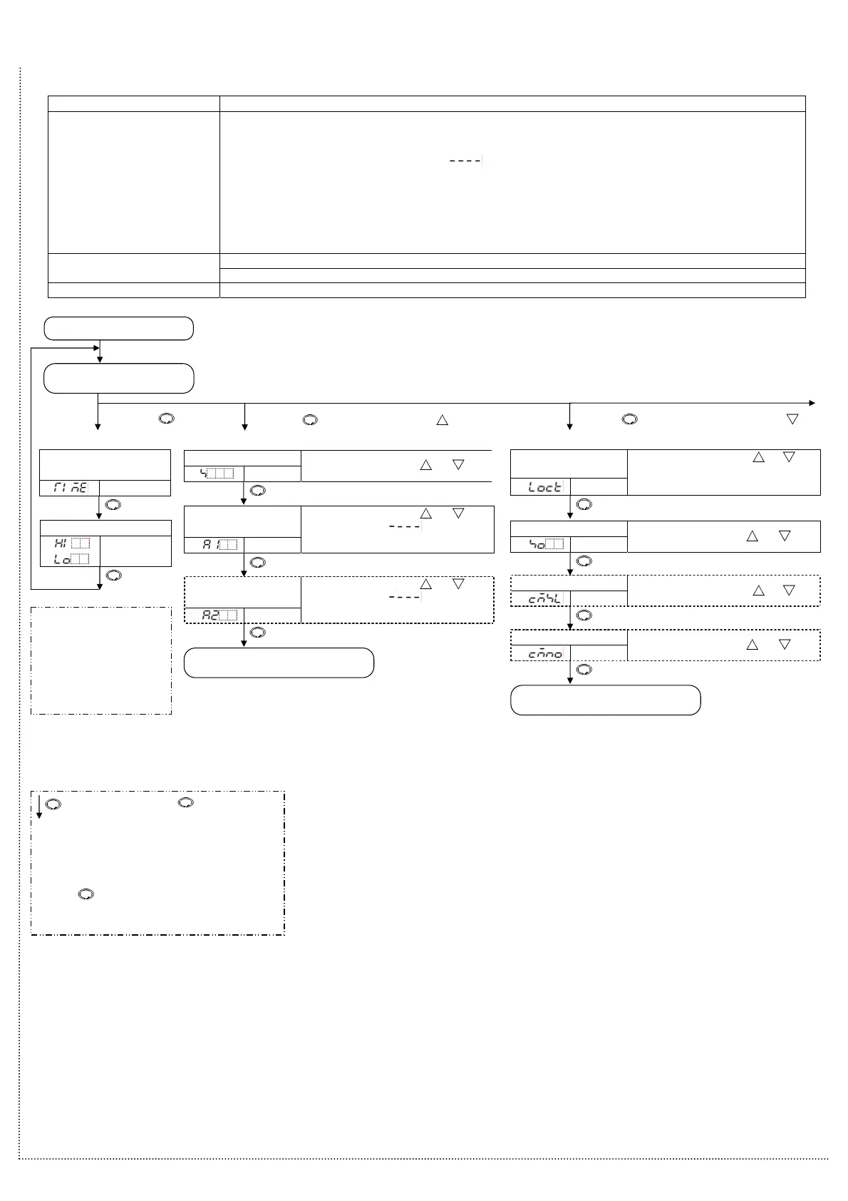
5. Settings
5.1 Operation flowchart
PV/SV display
[Main setting mode]
POWER ON
Press the .
A1 value
PV SV
Value
• Set the value with the or key.
• Not available if
is selected
during A1 type selection
SV
PV
SV
SV
• Set the value with the
or key.
Set value lock
PV SV
Selection
• Make a selection with the
or key.
• Be sure to select Lock 3 when using
Serial communication.
Reverts to the PV/SV display.
Maximum(Minimum) value *1
PV
(
)
SV
Max. value
(Min. value)
EXCEEDED indicator
lighting duration time
PV
SV
Time
[Display mode]
Sensor correction
PV SV
Value
• Set the value with the
or key.
Communication protocol
PV SV
Selection
• Make a selection with the
or key.
Instrument number
PV SV
Value
• Set the value with the
or key.
7
Press the while holding down the .
Press the
for 3sec while holding down the .
[Sub settin
mode]
*1
Maximum (or Minimum)
value will be indicated if
high (or low) limit control
action is selected during
Limit control action
selection in the Setup
mode.
Reverts to the PV/SV display.
: This means that if the key is pressed,
the set value is saved, and the controller
proceeds to the next setting item.
• Setting items with dotted lines are optional and
they appear only when the options are added.
• If the
key is pressed for approx. 3sec, the
controller reverts to the PV/SV display mode from
any mode.
Outline of operation procedure
Set Input type, Alarm (type, value, etc.) and SV (desired value), following the procedures below. Setting item numbers (1) to (7) are indicated on the flowchart.
[Step 1 Operation before run] Turn the load circuit power OFF, and turn the power supply to the JCS-33A ON.
[Step 2 Setup mode]
Set Input type, Alarm type, etc. in the Setup mode.
(1) Input type: Select an input type. Refer to “Input type (character indication) and range” on page 7.
(2) A1 type: Select an alarm type. Refer to “Alarm type” on page 7.
[If an alarm type except for “
” is selected, items (3) to (5) will be indicated and they
can be set if necessary.]
Note: If an alarm type is changed, the alarm set value becomes 0 (0.0). Therefore it
is necessary to set it again.
(3) A1 action Energized/Deenergized: Select Alarm 1 action Energized or Deenergized.
(4) A1 hysteresis: Set A1 hysteresis.
(5) A1 action delayed timer: Set A1 action delayed timer.
(6) SV: Set SV (desired value) in the Main setting mode. [Step 3 Main setting mode]
(7) A1 value: Set action point of A1 output in the Main setting mode.
[Step 4 Run] Turn the load circuit power ON. Control action starts so as to keep the control target at the SV (Desired value).
6

 Loading...


