High limit alarm –(Scaling span) to scaling span Minimum
negative value:
–199.9 or –1999
Maximum
positive value:
999.9 or 9999
Low limit alarm –(Scaling span) to scaling span
High/Low limits alarm 0 to scaling span
High/Low limit range alarm 0 to scaling span
Process high alarm Scaling low limit value to scaling high limit value
Process low alarm Scaling low limit value to scaling high limit value
High limit with standby alarm –(Scaling span) to scaling span
Low limit with standby alarm –(Scaling span) to scaling span
High/Low limits with standby alarm 0 to scaling span
High/Low limits independent alarm 0 to scaling span
High/Low limit range independent
alarm
0 to scaling span
High/Low limits with standby
independent alarm
0 to scaling span
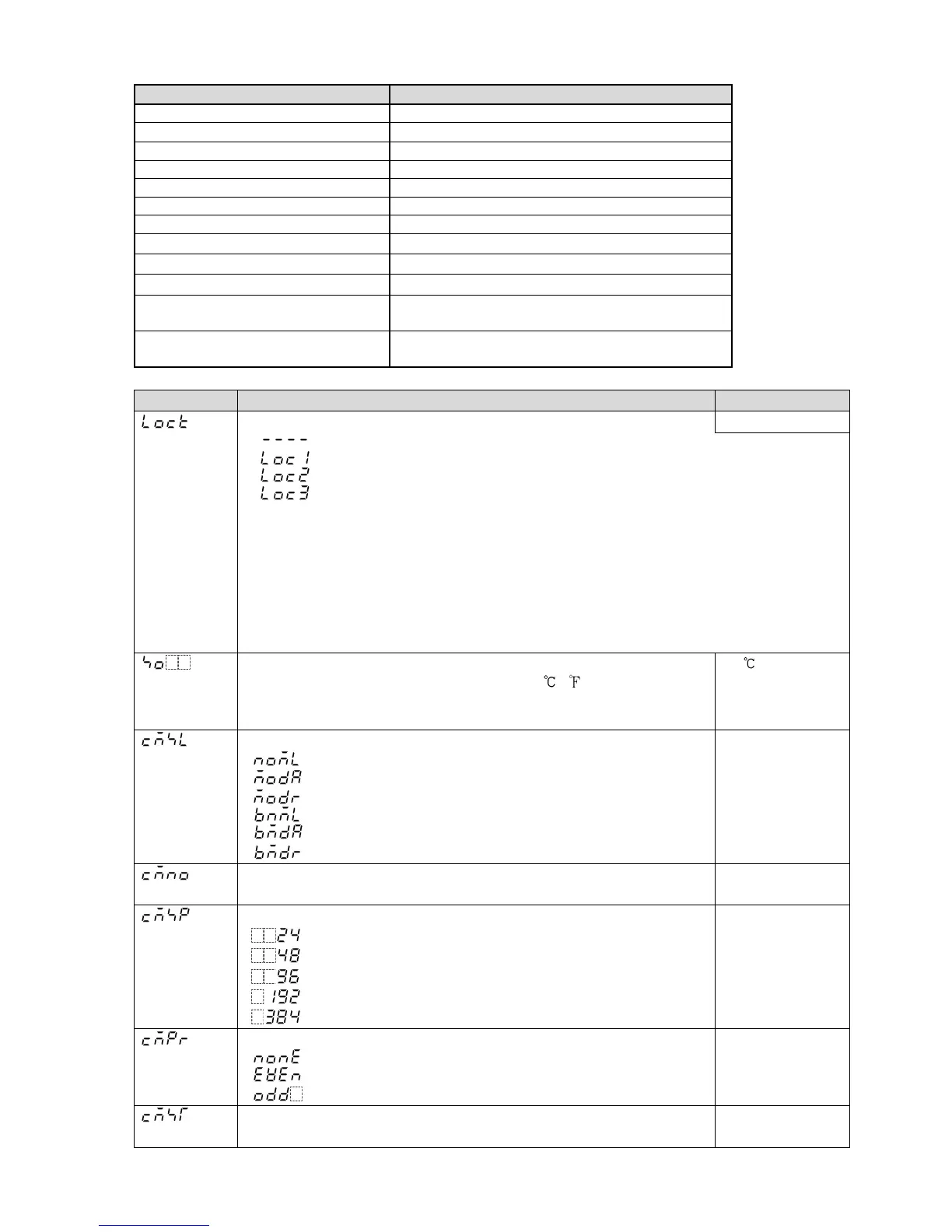
12.3 Auxiliary Function Setting Mode 1
Character Setting Item, Setting Range Factory Default
Set value lock Unlock
(Unlock): All set values can be changed.
(Lock 1): None of the set values can be changed.
(Lock 2): Only main setting mode can be changed.
(Lock 3): All set values – except input type and Controller/Converter – can be
changed. However, changed values revert to their previous values after power
is turned off because they are not saved in the non-volatile memory.
Do not change any setting item in Auxiliary function setting mode 2. If any item
in Auxiliary function setting mode 2 is changed, it will affect other setting items
such as the SV and Alarm value.
Be sure to select Lock 3 when changing the set value frequently via software
communication. (If a value set by the software communication is the same as
the value before the setting, the value will not be written in non-volatile memory.)
Sensor correction
Thermocouple, RTD input: –100.0 to 100.0 ( )
DC voltage, current input: –1000 to 1000 (The placement of the
decimal point follows the selection.)
0.0
Communication protocol
: Shinko protocol
: Modbus ASCII mode
: Modbus RTU mode
: Shinko protocol (Block read available)
: Modbus ASCII mode (Block read available)
: Modbus RTU mode (Block read available)
Shinko protocol
Instrument number
0 to 95
0
Communication speed
: 2400 bps
: 4800 bps
: 9600 bps
: 19200 bps
: 38400 bps
9600 bps
Parity
: No parity
: Even
: Odd
Even
Stop bit
1 or 2
1

 Loading...


