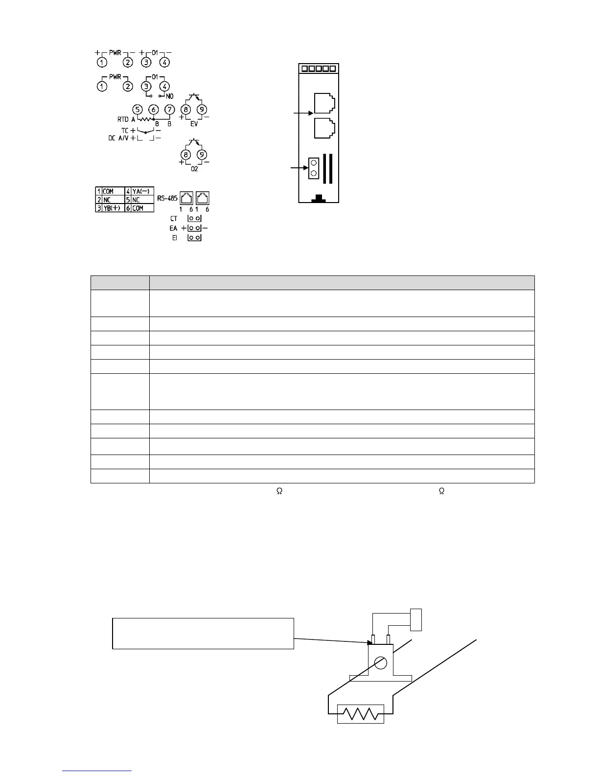
PWR
Power supply: 100 to 240 V AC or 24 V AC/DC
For 24 V DC, ensure polarity is correct.
O1 Control output OUT1
TC Thermocouple input
RTD Resistance temperature detector input
DC
(*1)
EV Event output
Outputs when Alarm, Loop break alarm or Heater burnout alarm output (W option) is
ON.
O2 Control output OUT2 [Heating/Cooling control output (DC option)]
RS-485 Serial communication (C5 option)
CT Current transformer input [Heater burnout alarm output (W option)]
EA External setting input (EA option)
EI Event input DI [Set value memory external selection (EI option)]
(*1) If direct current input (Externally mounted 50 shunt resistor) is designated, connect 50 shunt resistor (sold
separately) between input terminals.
4.2 Heater Burnout Alarm Output (W option)
This alarm is not available for detecting current under phase control.
Use the current transformer (CT) provided, and pass one lead wire of the heater circuit into the hole of
the CT. When wiring, keep the CT wire away from any AC source or load wires to avoid the external
interference.
(Fig. 4.2-1)
CT input socket
Power
supply
Heater
CT
Commu-
nication
C5
(RS-485)
Bottom of the unit
CT
EA
EI
Solder the connector harness W wire to
CT terminals. (There is no polarity.)
 Loading...