Shure LX4 Diversity Receiver
Service Procedures1925D1008 (BK)
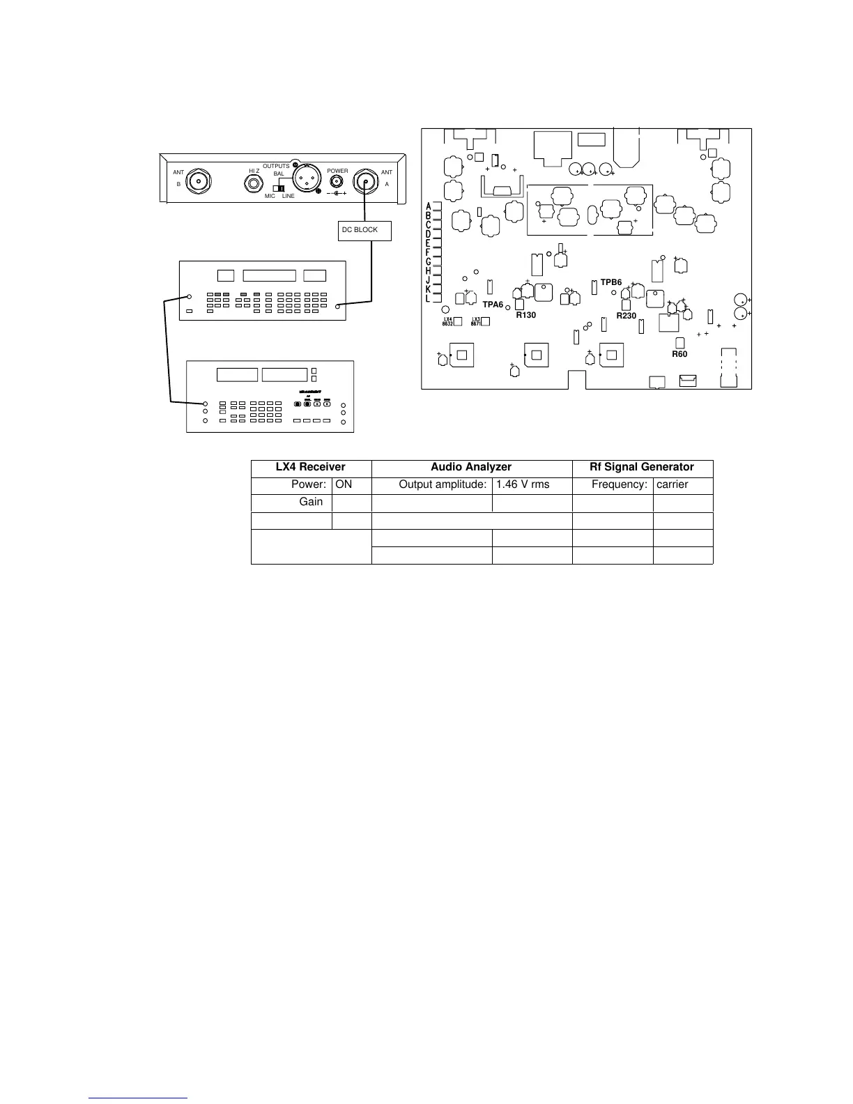
Noise Squelch Level Adjustment
RF SIGNAL GENERATOR
NOTE: DC VOLTAGES ARE PRESENT AT MOST
RF TEST POINTS. USE A DC BLOCK ON THE
RF SIGNAL GENERATOR TO PROTECT
TEST EQUIPMENT.
AUDIO ANALYZER
12.5 – 18.9 VDC
ANTANT
OUTPUTS
HI Z
BAL
MIC LINE
POWER
AB
TPA6
R130
TPB6
R230
R60
DC BLOCK
LX4 Receiver Audio Analyzer Rf Signal Generator
Power: ON Output amplitude: 1.46 V rms Frequency: carrier
Gain: Max Frequency: 50 kHz Modulation: FM
Squelch: Mid Filters: Mod source: EXT
400 Hz High-Pass: ON Amplitude: –60 dBm
30 kHz Low-Pass: OFF Deviation: 15 kHz
Figure 6. Noise Squelch Level Adjustment Test Setup
Note: The amplitude may have to be adjusted so that neither the HI EXT
nor the LO EXT LEDs on the rf signal generator are on. This amplitude
should be between 1.4 and 1.5 V rms.
1. Set the rf signal generator frequency to the same as the LX4, its
modulation to FM, its modulation source to EXT, its FM deviation
to 15 kHz, and its amplitude to –60 dBm.
2. Set the audio analyzer’s audio frequency to 50 kHz and its
amplitude to 1.46 V rms. Disengage 30 kHz lowpass filter.
3. Connect the output of the audio analyzer to the input of the
rf signal generator’s modulation input.
4. For channel A, adjust R130 for 2.0 ± 0.05 Vdc at TPA6 (positive
end of C18). For channel B, adjust R230 to 2.0 ± .05 Vdc at
TPB6 (positive end of C17).
5. Set the rf signal generator for 1 kHz modulation, amplitude to
–50 dBm, with 15 kHz deviation. Engage 30 kHz lowpass filter.
6. Measure total harmonic distortion (THD). Adjust R60 for
minimum distortion at the unbalanced output. Distortion should
be < .75%.
7. Remove the external modulation from the rf signal generator.
Repeat this test for channel B.
 Loading...


