Shure LX4 Diversity Receiver
20
Service Procedures
25D1008 (BK)
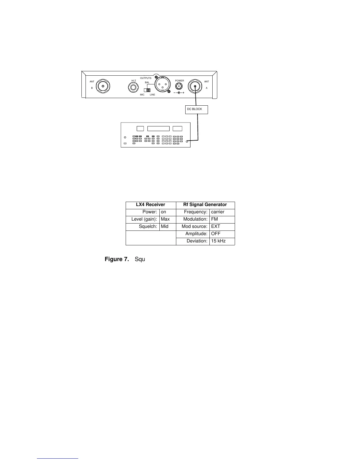
Squelch Adjustment Test
RF SIGNAL GENERATOR
NOTE: DC VOLTAGES ARE PRESENT AT MOST
RF TEST POINTS. USE A DC BLOCK ON THE
RF SIGNAL GENERATOR TO PROTECT
TEST EQUIPMENT.
12.5 – 18.9 VDC
ANTANT
OUTPUTS
HI Z
BAL
MIC LINE
POWER
AB
DC BLOCK
LX4 Receiver Rf Signal Generator
Power: on Frequency: carrier
Level (gain): Max Modulation: FM
Squelch: Mid Mod source: EXT
Amplitude: OFF
Deviation: 15 kHz
Figure 7. Squelch Adjustment Test Setup
1. Remove the jumper between TPB7 (TPA7) and ground.
2. Set the rf signal generator output to minimum (or OFF).
3. Increase the output level until the appropriate diversity LED is
illuminated. This should occur with an rf input level between
–105 and –89 dBm (nominally, –100 dBm).
Repeat this test for channel B.
 Loading...


