4
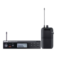
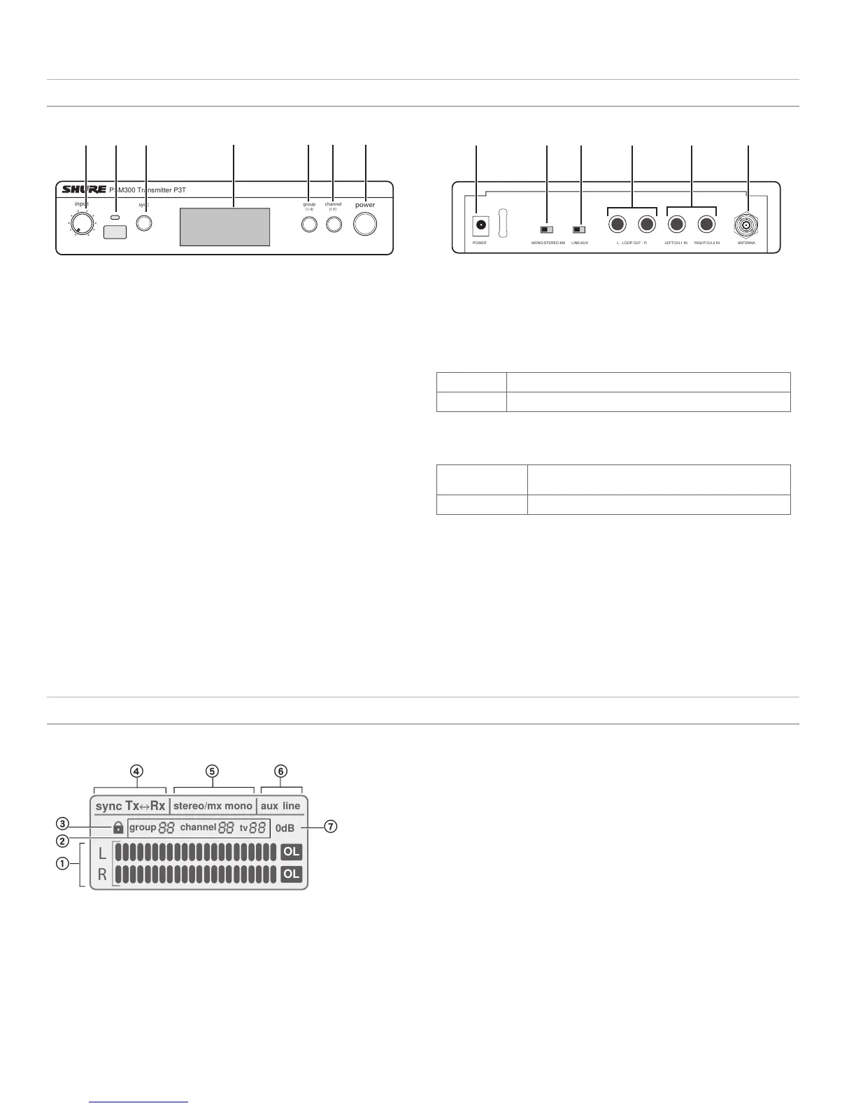
P3T Transmitter Front and Rear Panels
⑧ Power Input
Connect the supplied Shure PS23 external power supply
⑨ Mono/Stereo-MX Switch
StereoMX
Sends a two-channel stereo mix to the receiver
Mono
Sends a summed audio mix to both receiver channels
⑩ Line/Aux Switch
Adjust the input sensitivity using the following as a connection reference:
Aux (-10 dBV):
Consumer audio devices, such as computers or portable
media players
Line (+4 dBu):
Mixers or other professional audio devices
⑪ Loop Outputs (¼ Inch TRS, Balanced)
Connect outputs to additional PSM systems or other audio devices
⑫ Audio Inputs (¼ Inch TRS, Balanced)
Connect to mixer outputs or other audio sources for monitoring by the
performers
⑬ BNC Antenna Connector
Connect the supplied ¼ wave antenna, directional antenna, or a Shure
P3AC antenna combiner
power
group channel
sync
PSM300 Transmitter P3T
(1-F)
(1-9)
input
P3T Front Panel
① Input Level Control
Adjusts the level of the incoming audio signal
② IR Sync Window
Sends and receives group/channel data to sync receivers with
the transmitter
③ Sync Button
Press to synchronize the transmitter and receiver to the same
group and channel
Note:
Sync data is sent through the IR sync window
④ LCD Display
Displays audio, RF, and system information
⑤ Group Button
Press to scroll through group settings
⑥ Channel Button
Press to scroll through channel settings
⑦ Power
Turns power on or off
P3T Transmitter Display
L
R
OL
OL
sync
Tx Rx
stereo/mx mono
aux
line
0dB
group
channel
tv
① Audio Input Meter
Indicates the audio signal level
② Group / Channel / TV Setting
Displays selected group and channel settings and the
corresponding television channel
Note:
the TV indicator only applies to U.S.A. channels, and remains
blank in other regions
③ Lock Status
To lock or unlock the controls, press and hold the group and channel buttons
until the lock icon appears/disappears.
④ Sync Status
Appears after a successful sync between the transmitter and receiver. The
direction of the sync is shown as Tx>Rx (transmitter sends frequency to
receiver) or Tx<Rx (receiver sends frequency to transmitter).
⑤ Stereo-MX / Mono Mix
Indicates whether the audio sent to the receiver is a single or two-channel mix
(corresponds to the Stereo-MX/Mono switch on the rear panel).
⑥ Aux / Line Mode
Indicates the input sensitivity setting (corresponds to the Aux/Line switch on
the rear panel)
⑦ 0 dB Indicator
Turns on when input signal reaches 0 dB. Refer to the section on adjusting gain
and listening volume for information on how to use this icon.
① ②
③
④
⑤ ⑥ ⑦
⑧
⑨
⑩
⑪ ⑫
⑬
MONO/STEREO-MX LINE/AUX LEFT/CH.1 IN RIGHT/CH.2 INL - LOOP OUT - R ANTENNAPOWER
P3T Rear Panel
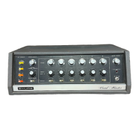
▇ Hardware
 Loading...