Shure U4D Dual Diversity UHF Receiver
19 25D1062 (AG)Service Procedures
Alignment
Align Receivers 1 and 2 separately. Receiver 1 is on the left and
Receiver 2 is on the right when looking at the front panel.
Equipment setup for the alignment procedure is sequential.
Test Setup
1. Remove the top cover from the U4D receiver.
2. To reduce the risk of electrical shock, do not touch or short any
components in the receiver switching power supply. The heat
sink on the power supply and all ac wiring contains hazardous
voltages.
3. Dc voltages are present at most rf test points. Use dc blocks on
the rf signal generator to protect the test equipment.
4. Use RG58 or any other low loss 50 Ω cables for all rf connec-
tions. Keep test cables as short as possible. Include insertion
loss of cables and connectors when making rf measurements.
5. Remove the network board.
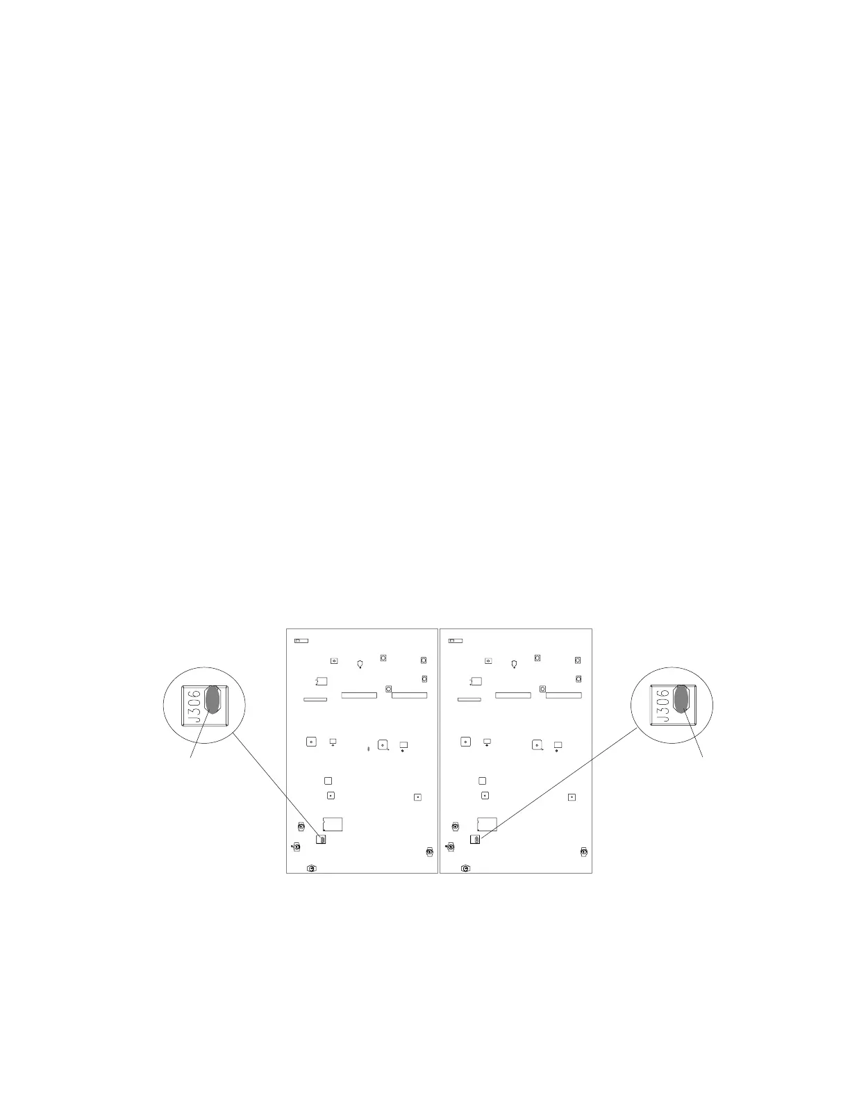
RECEIVER 1 RECEIVER 2
SOLDER JUMPER
SOLDER JUMPER
S201
S201
J306
J306
Figure 4. U4D Receiver Solder Jumper Locations