Shure U4D Dual Diversity UHF Receiver
25 25D1062 (AG)Service Procedures
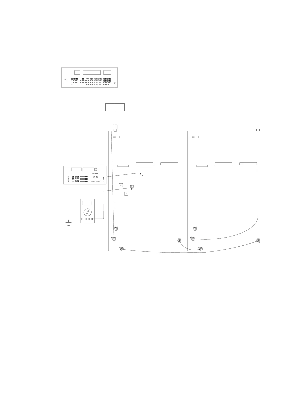
THD Verification and RSSI Adjustment (Channel A)
TP306 AUDIO CH A
TP328 RSSI CH A
R355
P202P202
P203
S201
ANTENNA A IN
P202
P202
P203
S201
ANTENNA B IN
RF SIGNAL GENERATOR
AUDIO ANALYZER
DC VOLTMETER
NOTE: DC VOLTAGES ARE PRESENT
AT MOST RF TEST POINTS. USE A DC
BLOCK ON THE RF SIGNAL GENERATOR
TO PROTECT TEST EQUIPMENT.
DC BLOCK
(OFF)
(OFF)
J302
L310 for PCB 34A8507
L311 for PCB 34A8703
Figure 9. Channel A RSSI Alignment
1. Change the rf signal generator Level to –50 dBm.
2. Measure the total harmonic distortion (THD) at TP306
(U305 pin 7). It should be less than 0.5%. If not adjust L310 for
PCB version 34A8507 or adjust FL311 for PCB version 34A8703
to minimize the distortion.
3. Adjust R355 for Vrssi at the wiper (TP328). The Vrssi should be
2.75 ± 0.1 Vdc for 34A8507F and earlier PCB versions.The Vrssi
should be 2.3 ± 0.1 Vdc for 34A8507G and later versions of the
board and the 34A8703 PCB version.