Shure U4D Dual Diversity UHF Receiver
27 25D1062 (AG)Service Procedures
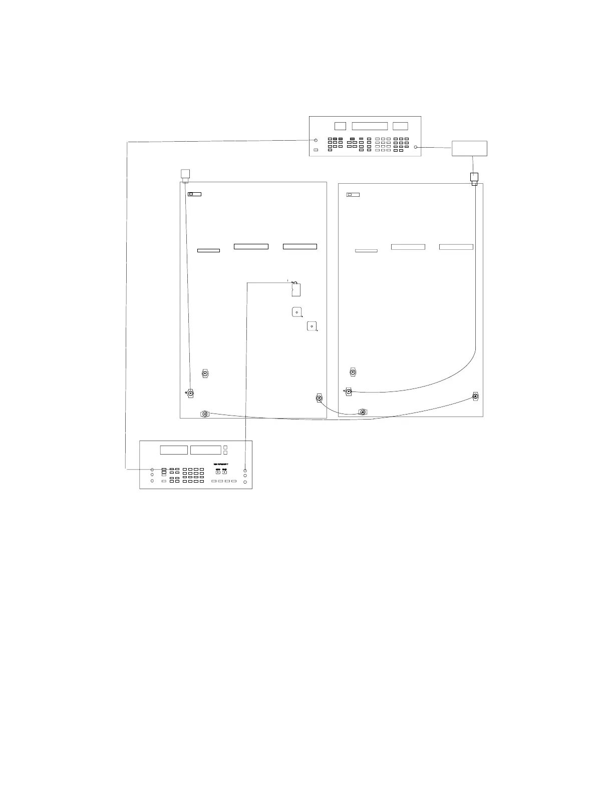
FM Detector Quadrature Coil Alignment (Channel B)
AUDIO ANALYZER
P202
P202
P203
S201
RF SIGNAL GENERATOR
DC BLOCK
P202
P203
L304 for PCB 34A8507
P202
S201
ANTENNA A IN
ANTENNA B IN
NOTE: DC VOLTAGES ARE PRESENT
AT MOST RF TEST POINTS. USE A DC
BLOCK ON THE RF SIGNAL GENERATOR
TO PROTECT TEST EQUIPMENT.
J302
TP308
(OFF)
(OFF)
FL313
for PCB
34A8703
U310
Figure 11. Channel B FM Detector Quadrature Coil Alignment
1. Set the rf signal generator Level to –86 dBm and the Deviation
as follows. If necessary, readjust the amplitude so HI EXT and
LO EXT lights turn off.
UA, UB,MA, MB, MC, MD: 45 kHz deviation at 1 kHz modulation
KK: 40 kHz deviation at 1 kHz modulation
II: 28 kHz deviation at 1 kHz modulation
2. Connect the rf signal generator to the ANTENNA B input.
3. Connect the audio analyzer to U310, pin 7 (TP308).
4. For PCB version 34A8507 tune L304 for maximum audio output
at TP308.For PCB version 34A8703 tune FL313 for maximum
audio output at TP308. The low limit is 250 mVrms. There is no
high limit.