Shure U4D Dual Diversity UHF Receiver
7 25D1062 (AG)Circuit Description
Display Board Interconnect with Rf-Audio Board
Integrated ribbon cable connector P102 interfaces with the rf-audio
board and the networking Interface board through the display board. Pin
assignments for the P102 connector are presented in the table below.
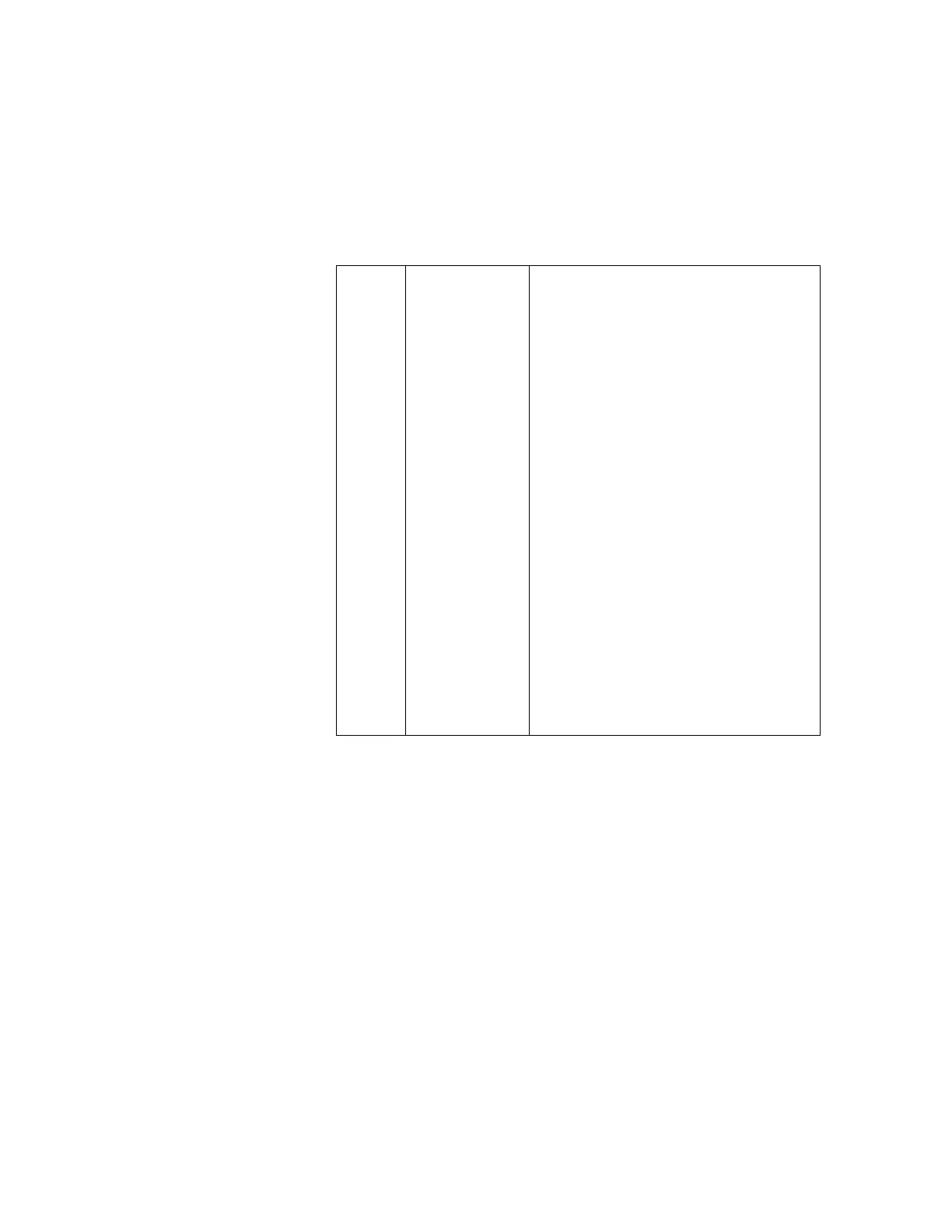
Table 1
P102 Interconnect Pin Assignments
PIN NO. SIGNAL NAME DESCRIPTION
1 D+5V +5V power supply to the Digital Board
2 DLOW_BATT Analog voltage representing TX battery level
3 DSQUELCH Data signal to U215 squelch D/A
4 GND Input power ground to the Digital Board
5 DLE Data Load Enable to U309 PLL Synthesizer
6 DRSSI_CH_A Chan. A rf Received Signal Strength Indicator
7 DD Data signal to U309 PLL Synthesizer
8 DLEDA Diversity LED A drive signal input
9 DCK Clock signal to U309 PLL Synthesizer
10 DLEDRET Diversity LED A and B common return
11 DRSSI_CH_B Chan. B rf Received Signal Strength Indicator
12 DLEdB Diversity LED B drive signal input
13 DAUDMTR Audio metering analog signal input
14 N141 Audio potentiometer return to the Audio Board
15 DSCL Clock signal to U215 squelch D/A
16 N142 Audio potentiometer wiper to the Audio Board
17 DLONE_W_OUT Interrupt output to the Networking Interface
18 N143 Audio potentiometer input from the Audio Board
19 DSDO Networking Serial Data Output
20 DLONE_W_INT Interrupt input from the Networking Interface