7
Hardware Configuration
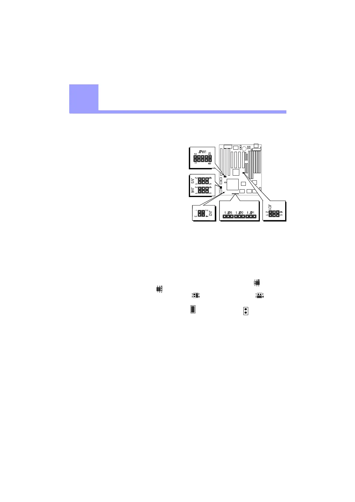
Jumper Setting
Jumper pin headers show on right side
are used to configure system clock,
CPU multiplier and CPU voltages.
System Clock - JC1
JC1 is a 6-pins header jumper which
is used to adjust System Clock from
50MHz to 83 MHz.
CPU Multiplier - JP1, JP2 and JP3
JP1, JP2 and JP3 are 3-pins header
jumper which is used to adjust CPU core multiplier from 1.5X to 5.5X.
CPU Voltages
JPW1, JV2, JV3 and JV4 are used to adjust onboard voltages output from Switching
type regulators to CPU by inserting or removing mini jumper from pin headers.
Those hardware settings are made through the use of jumper caps to connect jumper
pins on the main board. The jumpers will be show graphically such as to connect
pins 3&4 and 5&6, and to connect pins 1&2 and 3&4 for six pin jumpers.
Jumpers will be show graphically such as to connect pins 2&4 and to
connect pins 3&4 for four pin jumpers.
Jumpers with two pins will be shown as for Short (On) and for Open (Off).
To connect the pins, simply place a plastic jumper cap over the two pins as dia-
gramed.
2
2