www.Siargo.com FS4001 User Manual
5. Digital communication descriptions
5.1 I
2
C interface
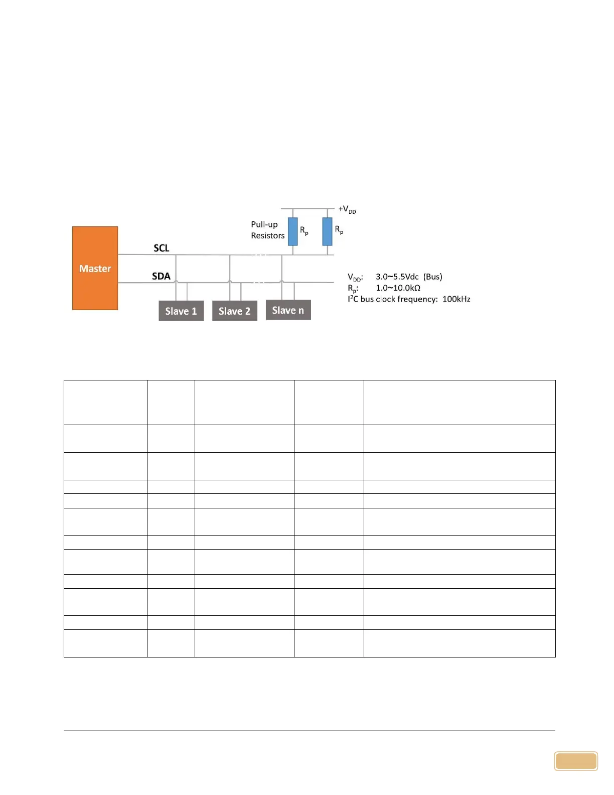
5.1.1 I
2
C interface connection diagram
5.1.2 I
2
C interface command description
Bit 0 is R/W flag bit; Bit 1~ Bit 7 are
available.
Write the gas
correction factor
Int16, the default value is 1000 for air
1 byte, ensure no-flow conditions
Int32(/1000 SLPM)+CRC
CRC=(Byte1)xOR(Byte2)x(OR(Byte3)XOR(byte4)
Read gas
correction factor
Int16, the default value is 1000 for air
Note: 1. The I
2
C address is set to Bit 7~Bit 1. E.g. if the I
2
C address is 1 (0000 001x), the write address will be
0x02 (0000 0010) and the read address will be 0x03 (0000 0011).