CDF600-2200 | SICK 8015922/1CC9/2021-07-12 • Subject to change without notice • SICK AG • Waldkirch • Germany • www.sick.com4
Device Description
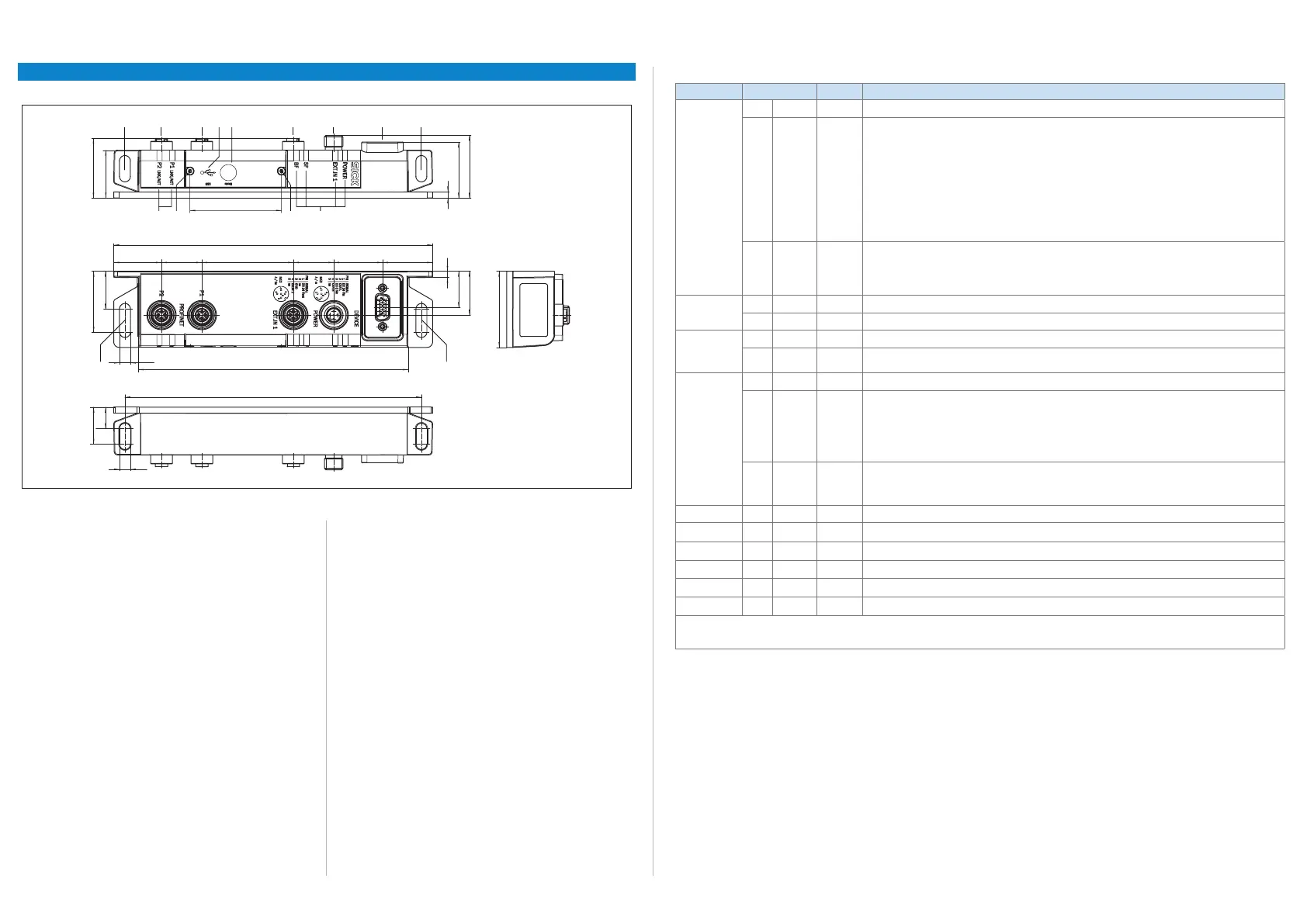
Device layout
39.5
40.7
36.3
4
All dimensions in mm
207
75864
2 3
99ß
ß
31
59.4
175.2
192.5
7.1
7.1
24.5
49.5
28.5
4
23.5
32.531.726.226.2 59.4(31)
24
14
CDF600-2200: View and dimensions
Legend:
1 Elongated drill hole (2 x), length 10 mm, unpainted, for mounting
with M6 screw
2 "P2 PROFINET" connection, 4-pin M12 female connector, D-coded
3 "P1 PROFINET" connection, 4-pin M12 female connector, D-coded
4 "USB" connection, 5-pin micro-B female connector, for conguration
and diagnostics, behind screw-mounted cover
5 "Mode" rotary encoding switch, for operating mode, behind screw-
mounted cover
6 "EXT. IN 1" connection, 5-pin M12 female connector, A-coded
7 "POWER" connection, 5-pin M12 male connector, A-coded
8 "DEVICE" connection, 15-pin D-SUB HD female connector with seal
9 LED (6 x), status indicator (POWER, EXT. IN 1, SF, BF, P1 LNK/ACT,
P2 LNK/ACT)
ß Screw (Torx T8), captive (2x), for cover
Elongated drill hole (2 x), length 15 mm, unpainted, for alternative
mounting with M6 screw
Optical status indicators
Indication LED Status Status
POWER – OFF Fieldbus module without supply voltage
Green Flashes
cycli-
cally
Sequence:
Once:
Only in operating mode 0 (proxy):
Following startup, the eldbus module searches for the ID sensor that supports proxy mode.
Twice:
The position of the rotary coding switch “Mode” was changed during operation.
This has no inuence on active operation.
Following a restart, the eldbus module then works in the operating mode that the new position of the
rotary encoding switch presents.
3 times:
Transparent operation of eldbus module (operating mode F) for rmware update of the ID sensor.
No communication with PROFINET IO.
O
Green ON Fieldbus module ready following start and initialization.
Operating mode 0 (proxy):
Communication established with ID sensor that supports proxy mode. The eldbus module is operational.
Operating mode 2 or 4 (gateway):
The eldbus module is operational.
EXT. IN1
–
OFF No power supply to external input 1
1)
O
Yellow ON Power supply to external input 1
1)
SF
–
OFF Fieldbus module without internal error
O
Red ON Operating mode 0 (proxy): Following startup, the eldbus module searches for the ID sensor that supports
proxy mode
BF
–
OFF Data exchange between eldbus module (IO device) and IO controller via PROFINET IO possible
O
Red ON No connection between eldbus module (IO device) and IO controller.
Possible causes:
– No electrical connection between eldbus module and PROFINET IO
– IO controller not available or switched off
– Wrong PROFINET name
– Wrong GSDML le used
– Wrong GSDML module selected
Red Flashes
cycli-
cally
Frequency 0.5 Hz
Possible causes:
– Parameterization error on IO controller (e.g., incorrect ID for IO device), no data exchange
– Error on IO controller affecting conguration with modules, no data exchange
P1 LNK/ACT
2)
–
OFF Fieldbus module not connected to any active network; no data trafc possible
P1 LNK
O
Green ON Fieldbus module connected with active network, e.g. with an Ethernet switch (switched-on)
P1 ACT
O
Orange ON LED ickers when the eldbus module is sending or receiving data
P2 LNK/ACT
2)
–
OFF Fieldbus module not connected to any active network; no data trafc possible
P2 LNK
O
Green ON Fieldbus module connected with active network, e.g. with an Ethernet switch (switched-on)
P2 ACT
O
Orange ON LED ickers when the eldbus module is sending or receiving data
SF = system failure, BF = bus failure.
1) Regardless of the logic assigned to the input via the SOPAS ET conguration software of the ID sensor.
2) There are 2 separate LEDs under the display window
O = illuminated; = ashing

 Loading...


