8015922/1CC9/2021-07-12 • Subject to change without notice • SICK AG • Waldkirch • Germany • www.sick.com CDF600-2200 | SICK 3
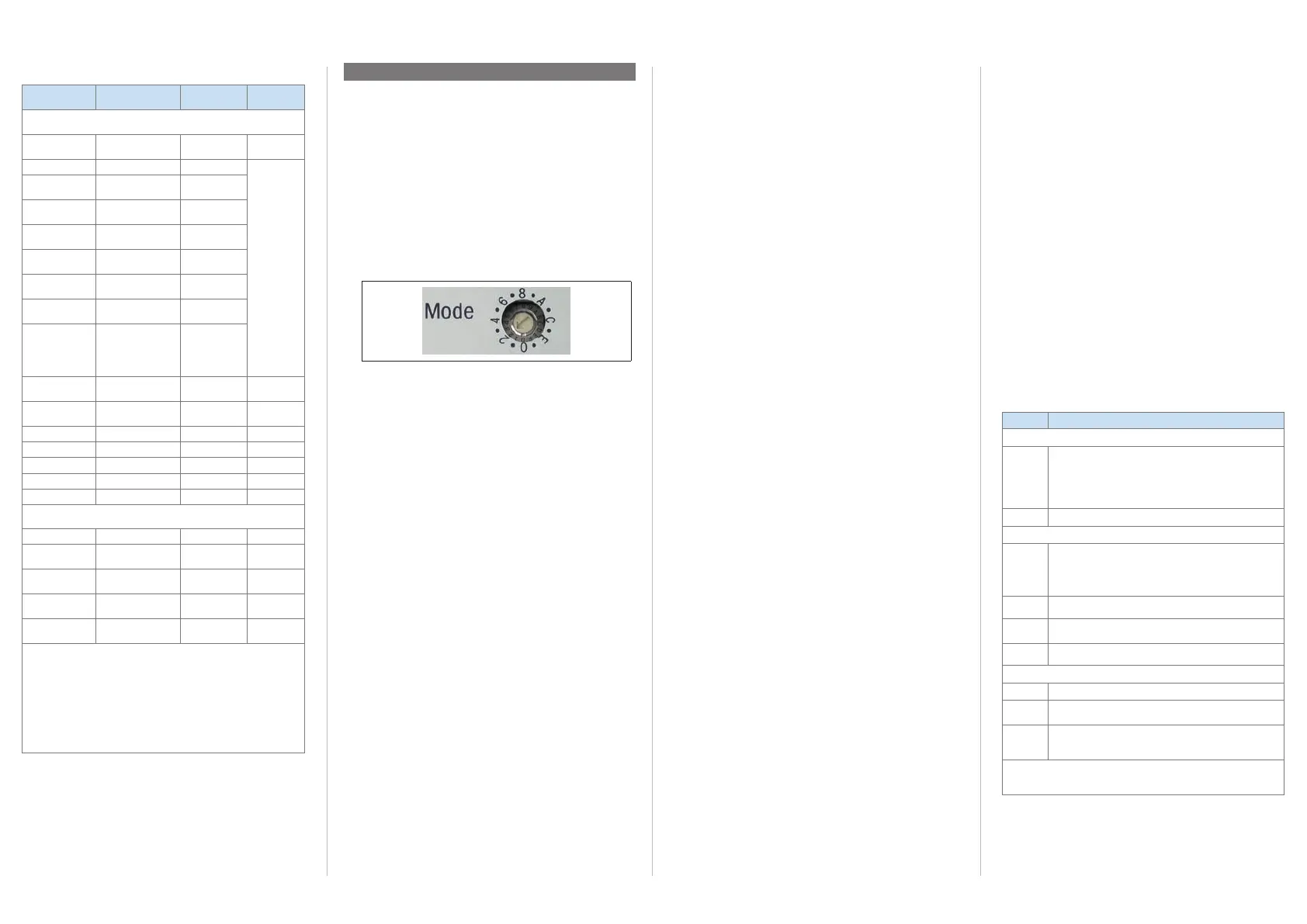
"Mode" rotary encoding switch (hexadecimal-coded)
Operating mode and communication mode for ID sensor to
be connected.
Position Operating mode/Functions
Proxy mode for ID sensor that supports proxy mode
0 Operation with ID sensor that supports proxy mode.
CDF600 communication mode.
(factory default).
Parameter cloning for ID sensor.
Conguration with parameterization modules of GSDML
le possible via IO controller.
1 Reserved for future use.
Gateway mode for ID sensor that supports gateway mode
2 Operation with ID sensor that supports gateway mode.
The eldbus module operates as a gateway.
CDF600 communication mode.
Data transmission rate between ID sensor and eldbus
module: 57.6 kBd.
3 Reserved for future use.
4 As position 2, but data transmission rate between
ID sensor and eldbus module: 9.6 kBd
5 Reserved for future use.
Additional functions
6 ... D
Reserved for future use
E
Operation for rmware update
1)
of eldbus module.
No communication with PROFINET IO.
F Transparent operation
2)
of the eldbus module for
rmware update of ID sensor.
No communication with PROFINET IO.
1) All LEDs ash simultaneously.
2) Data transmission rate 57.6 kBd.
"POWER" LED ashes cyclically 3 times.
CDF600-2200-relevant specications of ID sensors
ID sensor Supply
voltage
Power con-
sumption
1)
Firmware
version
ID sensors that support proxy mode
CLV61x FIELD-
BUS
DC 10 V ... 30 V 2.8 W, typical V. 1.21
CLV62x DC 10 V ... 30 V Max. 4.5 W V. 5.26
CLV63x
line/raster
DC 18 V ... 30 V 5 W typical
CLV63x
Line with SwSP
DC 18 V ... 30 V 6 W typical
CLV64x
line/raster
DC 18 V ... 30 V 5 W typical
CLV64x
Line with SwSP
DC 18 V ... 30 V 6.5 W typical
CLV65x
line
DC 18 V ... 30 V 8.5 W typical
CLV65x
Line with SwSP
DC 18 V ... 30 V 9.5 W typical
CLV63x ... 65x,
for heating
in addition
2)
DC 24 V ±10% Electronics
type-specic,
see above,
heating
max 30 W
CLV69x
3)
line
DC 18 V ... 30 V 15 W typical On request
CLV69x
3)
Line with SwSP
DC 18 V ... 30 V 17 W typical On request
Lector
®
620 DC 10 V ... 30 V 3 W typical On request
RFH62x DC 10 V ... 30 V Max. 5 W V. 3.10
RFH63x DC 10 V ... 30 V Max. 8 W V. 3.10
RFU62x DC 10 V ... 30 V
4)
8 W, typical
5)
V. 1.50
RFU63x DC 18 V ... 30 V < 20 W, typical V. 1.50
ID sensors that support gateway mode
Lector
®
64x/65x DC 24 V ± 20% 20 W typical –
IDM160 Transducer
DC 24 V/5 V
1.15 W typical –
IDM161 Transducer
DC 24 V/5 V
0.9 W typical –
IDM260 Transducer
DC 24 V/5 V
1.68 W typical –
IDM261 Transducer
DC 24 V/5 V
1.65 W typical –
1) Switching output without load
Power consumption of the eldbus module additionally < 5 W.
2) Connection diagram see & CDF600-22xx Fieldbus Module Technical Informa-
tion
(no. 8015924).
3) Without
conguration option via conguration module in the GSDML le.
4) DC 20 V to 30 V when using the RFU62x-101xx in ambient temperatures
of -20°C to -40°C.
5) Additionally max. 12 W from -20°C to -40°C.
Line with SwSP = Line scanner with oscillating mirror
Other ID sensors on request.
Step 3: Conguration
a. Overview of the conguration process
1. Set operating mode of the eldbus module using the
"Mode" rotary encoding switch.
2. Integrate the eldbus module in the IO controller.
3. Congure data communication in the eldbus.
4. Only ID sensor that supports proxy mode:
Use the SOPAS ET conguration software to set the
remaining functions of the eldbus module.
b. Setting the operating mode in the eldbus module
1. Open the side cover by unscrewing the two screws (ß)
( see “Device layout”, page 4). You can now access
the "Mode" rotary encoding switch.
Set the operating mode with the rotary encoding switch.
Position 0:
Fieldbus module operates as a proxy for an ID sensor
(e.g., bar code scanners from the CLV6xx product family).
Position 2 and 4:
Fieldbus module operates as a gateway for an ID sensor
that supports gateway mode (e.g., hand-held scanner);
data transmission rate dependent on switch setting.
List of modes that can be congured see ”””Mode”
rotary encoding switch (hexadecimal-coded)”, page 3.
The new setting is applied on the eldbus module when
the supply voltage is switched on.
Changes to the settings of the rotary encoding switch after
the power supply has been switched on are not applied in
data communication initially; however, the "POWER" LED
ashes cyclically 2 times.
To apply a change to the operating mode to the eldbus
module, restart both the eldbus module and the ID sen-
sor. In order to do this, switch off the supply voltage for the
eldbus module and switch it on again.
c. Conguring the eldbus module (resume here for
ID sensor that supports proxy mode)
The SOPAS ET conguration software for SICK identication
sensors is used as standard for the commissioning and fur-
ther conguration of the eldbus module with the ID sensor
that supports proxy mode connected to it.
The conguration of the eldbus module is integrated in the
menu of the respective ID sensor that supports proxy mode.
Installing and starting the conguration software
> Download and install the latest version of the SOPAS ET
conguration software, as well as current device descrip-
tion les (*.sdd), from the online product page for the
software: www.sick.com/SOPAS_ET by following the
instructions provided there.
Connect the PC to the eldbus module and switch on devices
1. Connect the PC (switched-off) as follows:
• Serial version of the ID sensor that supports proxy mode
with xed connecting cable (serial data interfaces only):
Use a data cable (no. 6036106, 2 m) to connect the
USB interface
4 of the eldbus module to the PC
interface (USB).
• Ethernet version of the ID sensor supporting proxy
mode:
Use a data cable (e.g., no. 6034414, 2 m) to connect
the Ethernet interface of the ID sensor to the Ethernet
network of the PC.
2. On the user side, switch on the supply voltage DC 10 V
to 30 V chosen according to the table on the left for the
eldbus module and the connected ID sensor.
Following initialization of the eldbus module and while
attempting to establish communication with the ID sensor,
the green "POWER" LED ashes. Once communication has
been established and the eldbus module is ready for op-
eration, the "POWER" LED lights up steady.
Meaning of LEDs see “Optical status indicators”, page
4.
3. Switch on PC and start conguration software via the
"SOPAS" option. Path: Start > Programs > SICK > SOPAS
ET Engineering Tool > SOPAS.
4. Start communication with the ID sensor with SOPAS ET as
described in the operating instructions for the connected
ID sensor that supports proxy mode. In order to do this,
select the desired communication interface for searching
in the connection wizard.
For the remaining steps in the process of conguring the
connected ID sensor, see & CDF600-22xx Fieldbus
Module Technical Information (no. 8015924).
d. Integrating the ID sensor in the IO controller and
conguring data communication on the eldbus
This section provides a brief overview of the general proce-
dure. This is covered in detail in relation to the ID sensor in
the & CDF600-22xx Fieldbus Module Technical Informa-
tion (no. 8015924).
Important!
The required GSDML les are available on the product site of
the eldbus module online: www.sick.com/CDF600-2.
ID sensor that supports proxy mode:
1. Integrate ID sensor as a new IO device in the IO controller
(e.g., PLC).
For this purpose, transfer the SICK sensor-specic GSDML
le for the corresponding ID sensor to the device descrip-
tion database of the IO controller.
See & CDF600-22xx Fieldbus Module Technical Infor-
mation (no. 8015924).
2. Specify the object trigger source and the output format of
the ID sensor for the eldbus using SOPAS ET.
ID sensor that supports gateway mode:
1. Integrate the eldbus module as a new IO device in the
IO controller master (e.g., PLC).
For this purpose, transfer the SICK-specic GSDML le for
the eldbus module to the device description database of
the IO controller.
2. IDM1xx and IDM2xx hand-held scanner:
Use the conguration codes to congure the hand-held
scanner for the eldbus module.
For more information, see & CDF600-22xx Fieldbus
Module Technical Information (no. 8015924).
3. Any ID sensor with RS-232 interface:
Connect RS-232 interface to pin 2, 3, 5 of the eldbus
module (DEVICE connection).
Set communication parameters to:
- Datastring framing: STX and ETX
- Data format: 8 databits, no parity, 1 stop bit
- Data transmission rate: 9.6 kBd or 57.6 kBd according
to the selected position, 4 or 2, of the "Mode" rotary
encoding switch.

 Loading...


