8015922/1CC9/2021-07-12 • Subject to change without notice • SICK AG • Waldkirch • Germany • www.sick.com CDF600-2200 | SICK 5
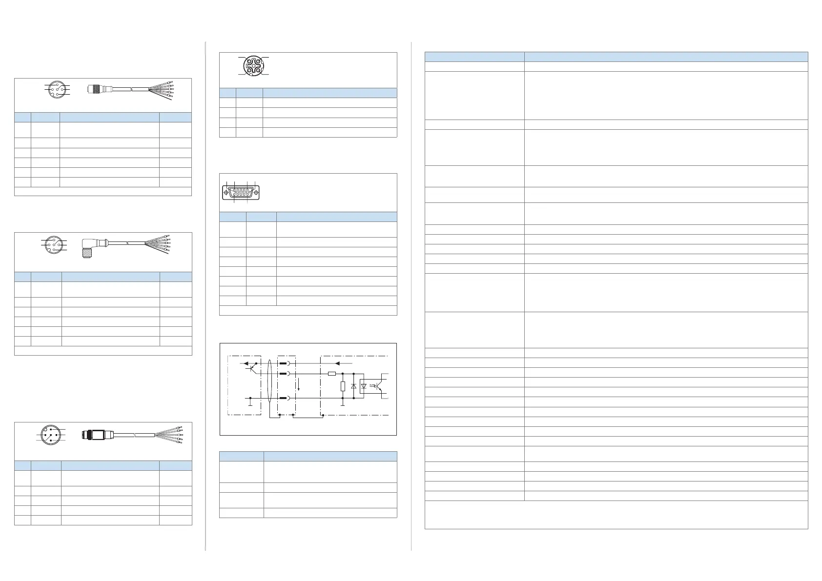
3. P1/P2 PROFINET connections
M12 - D / female connector
4
3
2
Pin Signal Function
1 TD
+
Sender+
2
RD+
Receiver+
3 TD
–
Sender–
4
RD–
Receiver
–
Pin assignment of both the 4-pin M12 P1/P2 PROFINET IO female
connectors (D-coded)
4. DEVICE connection
Pin Signal Function
1 DC 24 V
out
Supply voltage OUT (DC 10 V ... 30 V),
max 2 A
2 TxD (AUX) RS-232, sender
3 RxD (AUX) RS-232, receiver
5 GND Supply voltage ground
4, 6 ... 9 N. c. –
10 CAN H CAN bus
*)
11 CAN L CAN bus
*)
12 ... 15 N. c. –
*)
CAN-Bus only with support from ID sensor with CAN interface.
Pin assignment of the 15-pin D-SUB HD female connector DEVICE
Wiring of the “EXT. IN 1” switching input
Ext. In 1
*)
GND
GND
V
S out
3
4
1
V
S
= DC 10 V ... 30 V
V
in
V
S
V
S
6.64 K
3.32 K
Example wiring of the EXT. IN 1 switching input
Features Description
Switching
behavior
Power at the input starts the assigned function in
the ID sensor that supports proxy mode
(default: level active high, debounce 10 ms)
Properties Can be wired, e.g., to PNP output of a trigger sensor
Electrical
values
Low: |V
in
| ≤ 2 V; |I
in
| ≤ 0.3 mA
High: 6 V ≤ |V
in
| ≤ 32 V; 0.7 mA ≤ |I
in
| ≤ 5 mA
LED "EXT. IN 1" Low: OFF High: ON
Specications of the EXT. IN 1 switching input
Overview of pin assignments and wire colors (cables)
1. POWER connection (supply voltage)
Cable no. 6036384 (5 m)
M12 - A / female connector
4
3
5
2
1
Illustration may differ
Pin Signal Function Wire color
1 DC 24 V
in
Supply voltage IN
(DC 10 V ... 30 V)
Brown
2 CAN L CAN bus
*)
White
3 DC 0 V
in
Supply voltage ground Blue
4 CAN H CAN bus
*)
Black
5 N. c. – Gray
– – Shield Metal
*)
CAN-Bus only with support from ID sensor with CAN interface.
Pin assignment of the 5-pin M12 POWER female connector (A-coded,
straight) of the cable and wire colors of the open cable end
Cable no. 6049456
1)
, SPEEDCON (3 m)
M12 - A /
4
3
5
2
1
Illustration may differ
Pin Signal Function Wire color
1 DC 24 V
in
Supply voltage IN
(DC 10 V ... 30 V)
Brown
2 CAN L CAN bus
*)
White
3 DC 0 V
in
Supply voltage ground Blue
4 CAN H CAN bus
*)
Black
5 N. c. – Gray
– – Shield Metal
*)
CAN-Bus only with support from ID sensor with CAN interface.
Pin assignment of the 5-pin M12 POWER female connector (A-coded,
90° angle) of the cable and wire colors of the open cable end.
1) Other lengths: no. 6049455 (1.5 m), no. 6049457 (5 m),
no. 6049458 (10 m)
2. EXTERNAL IN 1 connection (digital switching input)
Cable no. 6026133 (2 m)
4
3
5
2
1
Illustration may differ
Pin Signal Function Wire color
1 DC 24 V
out
Supply voltage OUT
(DC 10 V ... 30 V), max. 400 mA
Brown
2 N. c. – White
3 GND Supply voltage ground Blue
4 EXT. IN 1 External input 1 Black
5 N. c. – Gray
Pin assignment of the 5-pin M12 male connector EXT. IN1 (A-coded,
straight) of the cable and wire colors of the open cable end
Technical Specications
Model name CDF600-2200 (no. 1062460)
Function Proxy or gateway for PROFINET IO networks
Supported SICK identication sensors ID sensors that support proxy mode:
CLV61x FIELDBUS, CLV62x ... 65x, CLV69x bar code scanners
Lector
®
620 image-based code reader
RFH620 and RFH630 RFID read/write devices (both HF) RFU62x and RFU63x (both UHF)
ID sensors that support gateway mode:
Lector
®
64x and Lector
®
65x image-based code readers
IDM1xx and IDM2xx hand-held scanner
Station type PROFINET IO device
Supported communication modes
Dependent upon sensor type, see & CDF600-22xx Fieldbus Module Technical Information (no. 8015924)
In operating mode 0 (proxy):
CDF600 mode with handshake, CDF600 mode without handshake
In operating mode 2 or 4 (gateway):
CDF600 mode with handshake
PROFINET IO data interface 2-port Ethernet in accordance with IEEE 802.3 (data transmission rate 100 MBit/s, full-duplex transmission,
2-port switch, auto negotiation, auto crossover).
Maximum data length limited to 4000 bytes by communication mode (fragmentation protocol).
AUX data interface
(DEVICE connection)
Serial (RS-232), 57.6 kBd or 9.6 kBd, for data communication with the ID sensor
CAN bus data interface
(POWER connection)
Connection of an ID sensor via the eldbus module as a last participant on on a CAN bus.
10 kBit/s .... 1 MBit/s, CAN sensor network. CAN network in the eldbus module with termination resistor already
connected on one side
USB data interface USB 2.0 for conguration and diagnostics
Digital switching inputs 1 x V
in
= max. 32 V, can be wired, e.g., with PNP output of a trigger sensor
Digital switching outputs –
Optical indicators 6 x LED
1)
Parameter cloning Integrated (conguration data of the connected ID sensor, in proxy mode)
Electrical connections 1 x 15-pin. D-SUB HD female connector (DEVICE), with seal
1 x 5-pin M12 male connector (POWER), A-coded
1 x 5-pin. M12 female connector (EXT. IN 1), A-coded
2 x 4-pin. M12 female connector (P1/P2 PROFINET), D-coded
1 x USB female connector, type micro-B (covered)
2)
Supply voltage IN DC 10 V ... 30 V, reverse polarity protected.
Voltage range may be restricted by connected ID sensor
see “”, page 2
Power supply unit: SELV according to EN 61010 and Class 2 (UL 1310)
Protection of the supply cable with max. 3 A
Supply voltage OUT (DEVICE) As supply voltage IN, not short-circuit-protected.
Power consumption < 5 W (no ID sensor connected, switching input "EXT. IN 1" not connected)
Fieldbus module current consumption Max. 250 mA
Current ow to ID sensor 2 A, max. (internal fuse, cannot be accessed)
Housing/
housing color Non-varnished cast aluminum, light-blue labeling lm (RAL 5012)
Electrical safety IEC 61010-1:2010 + Cor.:2011
Enclosure rating IP 65, acc. to EN 60529:1991-10 + A1:2000-02
3)
Electrical protection class III
Dimensions 207 mm x 49.5 mm x 40.7 mm (without connected cables)
Weight 360 g
Electromagnetic compatibility (EMC) Radiated emission: acc. to EN 61000-6-3:2007-01 + A1:2011-03
Shock resistance: acc. to EN 61000-6-2:2005-08
Vibration resistance/Shock resistance Acc. to EN 60068-2-6:2008-02 / acc. to EN 60068-2-27:2009-05
Ambient temperature Operation: -35°C ... +50°C / Storage: -35°C ... +70 °C
Permissible relative humidity Max 90 %, non-condensing
Mark of conformity CE, UL 60950-1 (E244281)
1) Under the two LNK/ACT display windows there are 2 separate LEDs
2) Only for conguration and diagnosis.
3) Under the following conditions:
When using a SICK scanner standard connection cable for the ID sensor. M12 male connectors of connected lines
are
clamped and unused connections are equipped with yellow, secured protective caps or plugs.
For detailed technical specications, see the Online data sheet on the product site on the web (www.sick.com/CDF600-2).

 Loading...


