3.2.3 Compatible sensor types
The safety relay is suitable for safety sensors and safety switches with volt-free output
cont
acts, e.g.:
•
Dual-channel safety command devices (emergency stop pushbutton, rope pull
switch, etc.)
•
Dual-channel, contact-based interlocking devices (safety locking devices and
safety switches)
•
Dual-channel, magnetic safety switches with reed contacts
3.2.4 Restart interlock
A restart interlock can be implemented with a reset pushbutton.
3.2.5 External device monitoring
Permanent external device monitoring can be implemented using external wiring.
3.2.6 Cross-circuit detection
A cross-circuit is detected on the safety capable inputs.
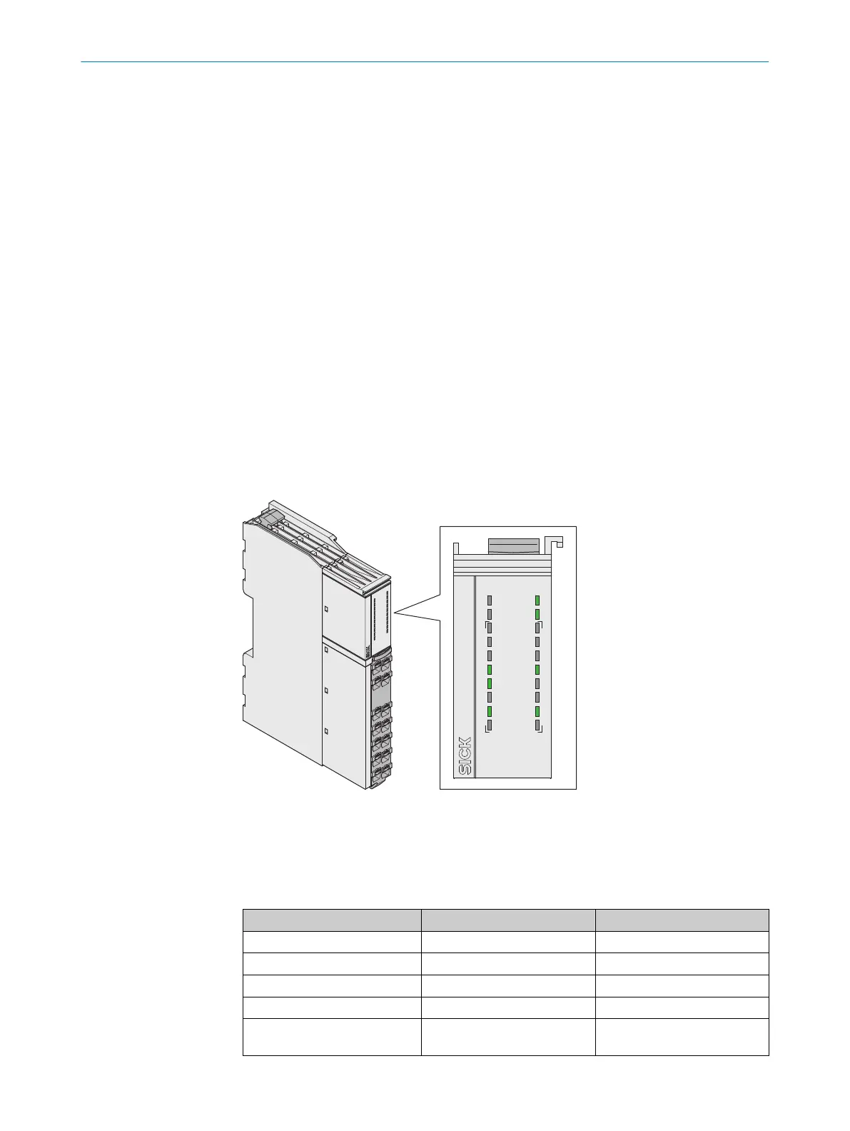
3.2.7 Status indicators
LEDs
PWR
OUT
1
3
2
3
I1
Y1
14
2
4
I2
Y2
A2
RELY
S1
X1
A1
R1
X2
PWR
OUT
13
23
I1
Y1
14
24
I2
Y2
A2
RELY
R1
A1
S1
X1 X2
Figure 2: LEDs
The labeled positions are only partially assigned LEDs. The positions and their labeling
(e
xcept for the upper 2 lines) also show the pin assignment of the terminals on the front
connector.
Table 1: Safety relay indicators
Labeling Color Function
PWR Green/Red Voltage supply
OUT Green Enabling current paths
I1 Green Safety capable input
I2 Green Safety capable input
S1 Green Reset pushbutton input, exter‐
nal de
vice monitoring (EDM)
3 PRODUCT DESCRIPTION
10
O P E R A T I N G I N S T R U C T I O N S | ReLy EMSS1 8020868/ZX84/2018-11-15 | SICK
Subject to change without notice