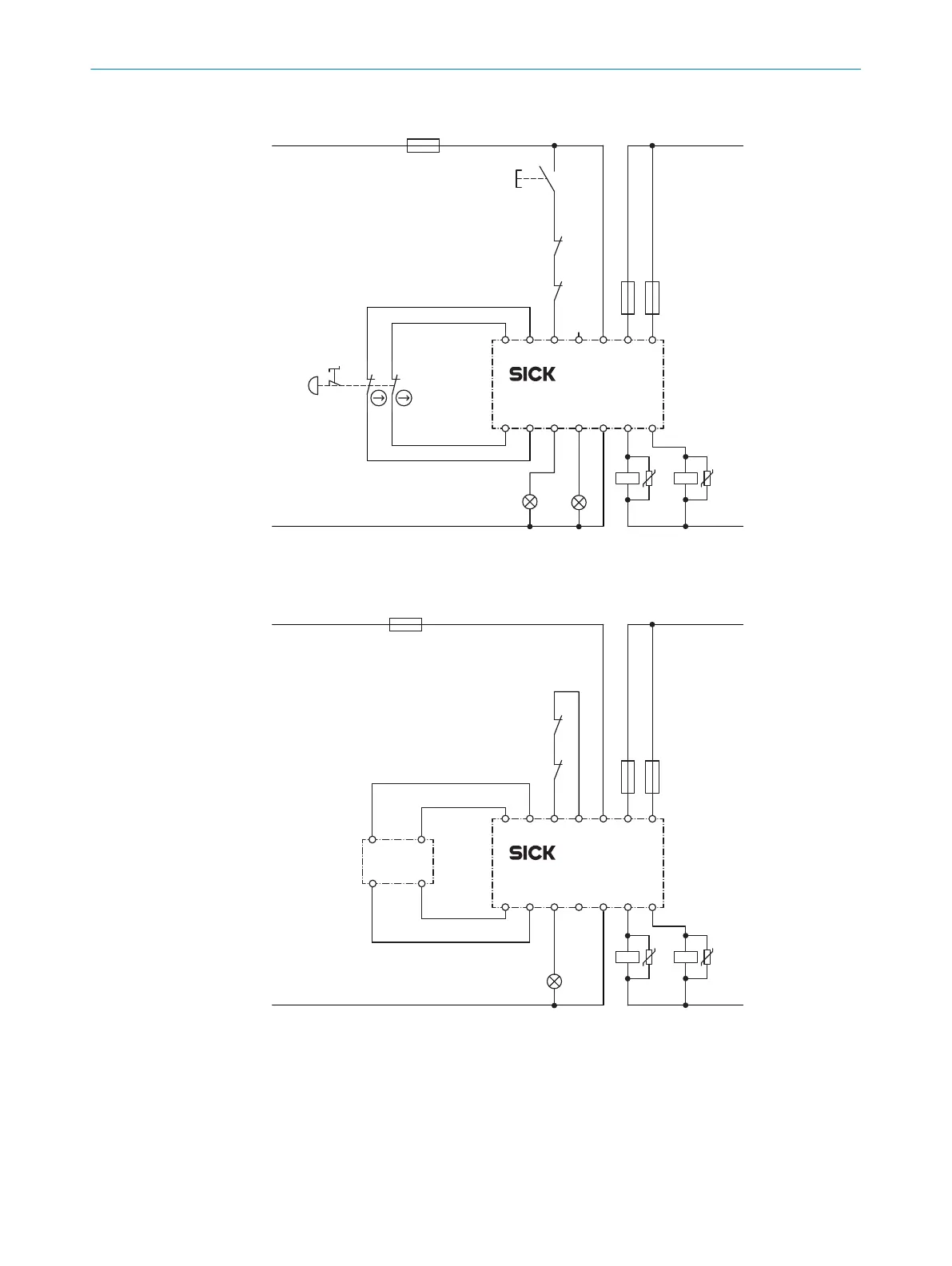
4.4.5 Connection diagrams
K2
K1
S1
X1 Y1 Y2 24X
2 A2 14
I1 I2 S1 A1R1 23 13
RLY3-EMSS1
F2 F1
L++24 V DC
0 V
k2
k1
Reset
F0
E210667/00/2018-11-15
State RES
Figure 4: ReLy EMSS1 connection diagram, with restart interlock and external device monitoring
(EDM)
K2
K1
X1 Y1 Y2 24X
2 A2 14
I1 I2 S1 A1R1 23 13
RLY3-EMSS1
F2 F1
L+
L–
+24 V DC
0 V
k2
k1
F0
E210668/00/2018-11-15
State
2
4
1
3
RE13
Figure 5: ReLy EMSS1 connection diagram, without restart interlock, with external device moni‐
t
oring (EDM)
4.5 Testing plan
The safety relay must be thoroughly checked by appropriately qualified safety personnel
dur
ing commissioning, after modifications, and at regular intervals, see "Thorough
check", page 23.
PROJECT PLANNING 4
8020868/ZX84/2018-11-15 | SICK O P E R A T I N G I N S T R U C T I O N S | ReLy EMSS1
15
Subject to change without notice
 Loading...