6.3 Pin assignments of electrical connections
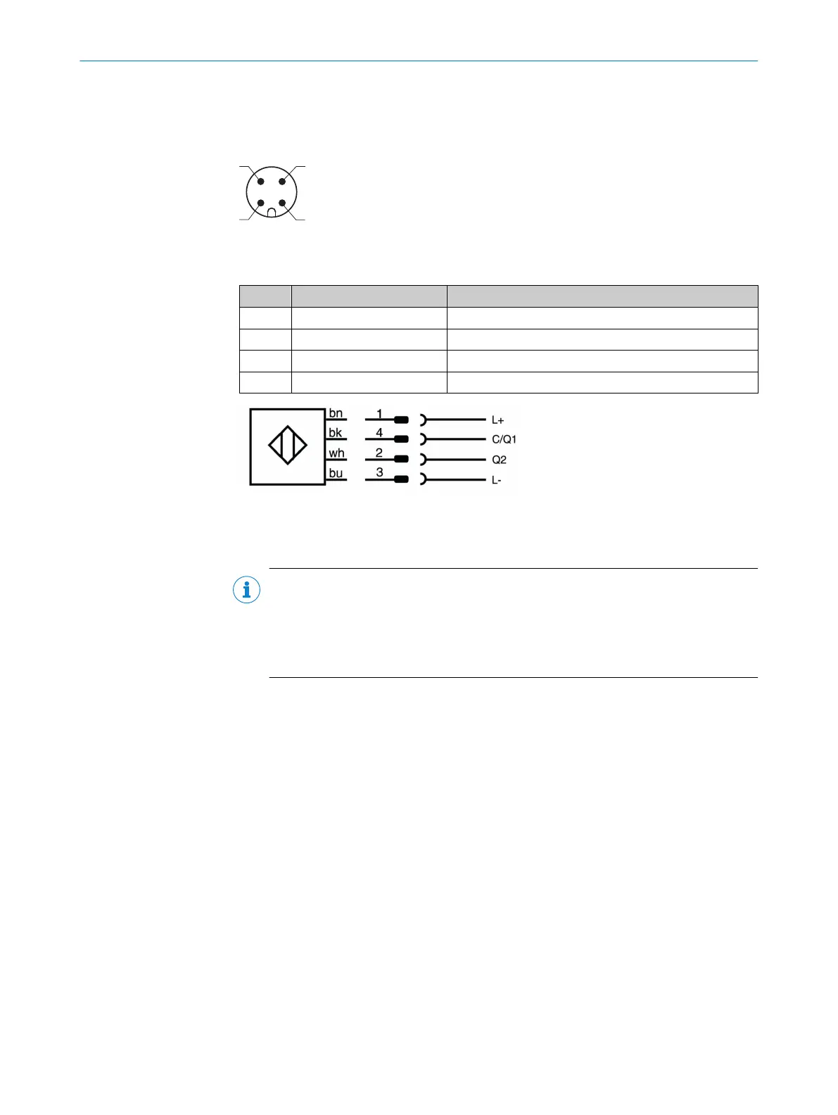
6.3.1 Connection 1: “IO-Link”
Figure 15: Male connector, M12, 4-pin, A-coded
Table 5: Pin assignment of the IO-Link connection (port class type A)
PIN Signal Function
1 L+ +24VDC (supply voltage)
2 Q2 Digital output 2
3 L– 0V (supply voltage)
4 C/Q1 IO-Link communication / digital output 1
6.4 Prerequisites
•
Use SICK IO-Link standard cables for the specified ambient temperature range.
NOTE
You will find the technical data for the cables on the product page.
The call is made via the SICK Product ID: pid.sick.com/{P/N}/{S/N}
{P/N} corresponds to the part number of the product, see type label.
{S/N} corresponds to the serial number of the product, see type label (if indicated).
•
Do not operate the device at ambient temperatures below 0°C when mounting or
connection work is being carried out.
•
Perform all connection work only in the ambient temperature range 0°C to
+80°C. Secure the connecting cables.
6.5 Behavior of the device when switched on
After application of the supply voltage and successful initialization, all device variants
can be addressed using a configuration tool such as the SOPAS ET configuration
software.
6 ELECTRICAL INSTALLATION
30
O P E R A T I N G I N S T R U C T I O N S | RFH5xx 8025309/1KDE/2023-12-19 | SICK
Subject to change without notice
 Loading...