Operating instructions IO-Link USB Master SiLink2 Master
ElectricalConnection
12 ©SICKAG•PresenceDetection•Subjecttochangewithoutnotice•8017387
WallPlugUsage Asstandard,aUSBportprovides500mAat5V.Withoutawallplug,the
SiLink2MasterIOLA2USsuppliesapprox.80mAat24V.ForlotsofIO-Link
devices,apowersupplyof80mAissufcient.
IftheIO-Linkdeviceneedsmorepower,e.g.,whenstartingup,thenyouwill
needtousethesuppliedwallplug.
Fig. 4: Wall plug pin assignment
5.3 ConnectionDiagram
5.3.1 USBConnectionDiagram
Fig. 5: Mini USB B connection diagram
Contact Signal Description
1 +5V VBUS+5VDC/500mA
2 D– Data–
3 D+ Data+
4 ID nc:notassigned
5 GND Ground(0V)
Table 2: Description Mini USB B
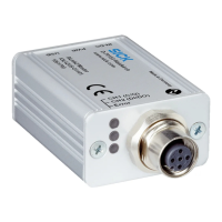
5.3.2 IO-LinkConnectionDiagram
5
Fig. 6: IO-Link connection diagram, M12 male connector, 5-pole, A-coding
Contact Signal Description
1 +24V Supplyvoltage:DC+24V
2 SIO SIO:CH2(DI/DO)
3 GND Supplyvoltage:0V
4 IO-Link IO-Link:CH1(C/Q)
5 – nc:notassigned
Table 3: Description IO-Link, M12 male connector, 5-pole, A-coding
 Loading...