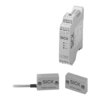
The SICK T4000 Standard is a transponder safety switch designed to monitor movable physical guards on machinery. This device ensures that machine operation in automatic mode is only possible when the guard is closed, and it triggers a stop command if the guard is opened while the machine is running.
Function Description:
The T4000 Standard safety switch operates based on a unique coding system. During commissioning, an actuator must be taught in at the sensor. The system allows for teaching in up to 8 actuators in succession, with only the most recently taught-in actuator being valid. When a guard is closed, the actuator moves towards the sensor. The sensor detects the actuator's code when it reaches the switch-on distance. If a valid, taught-in code is detected, the system activates the safety outputs (relay outputs) and the application diagnostic output (OUT) to HIGH. Conversely, when the guard is opened and the actuator moves out of the sensor's response range, the safety outputs and the application diagnostic output OUT are set to LOW.
The evaluation unit ensures a safe state in the event of any detectable fault. This is achieved through dynamic interrogation of the actuator and a redundant, diverse configuration of the safety electronics, combined with two safety outputs. The status of these safety outputs is internally monitored by positively guided N/C contacts (relay outputs). Any internal device faults are detected at the latest when the safe contacts are next requested to close (e.g., at machine start-up), at which point the safety switch transitions to a safe state. If a fault is detected, the safety circuit is switched off, the diagnostic output ERROR is set to HIGH, and the ERROR LED illuminates red.
Important Technical Specifications:
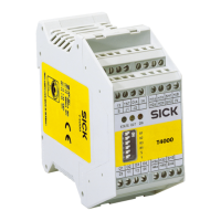
Evaluation Unit T4000-1RBA01:
- Performance Level: PL e (ISO 13849-1)
- Category: Category 3 (ISO 13849-1)
- PFHD (mean probability of a dangerous failure per hour): 4.3 × 10⁻⁸
- TM (mission time): 20 years (at maximum switching load)
- Type: Type 4 (ISO 14119)
- Actuator Coding Level: High coding level (ISO 14119)
- Switching Cycles/Year: 760,000 (typical), 153,000 (minimum), 34,600 (maximum)
- Diagnostic Coverage DC: 90%
- MTTFD (mean time to dangerous failure): 100 years
- Housing Material: Plastic PA6.6
- Dimensions: 114 x 99 x 22.5 mm³
- Weight: 0.2 kg
- Ambient Temperature: -20 °C to +55 °C (at UB = 24 V DC)
- Enclosure Rating: IP20
- Protection Class: III, contamination level 2
- Mounting: Mounting rail 35 mm in accordance with EN 60715
- Number of Sensors: 1 sensor per evaluation unit
- Connection Type: Plug-in screw terminals/coded
- Terminals: 0.14 mm² to 2.5 mm²
- Supply Voltage UB: 21 V DC (min), 24 V DC (typ), 27 V DC (max) (regulated, residual ripple < 5%)
- Current Consumption (with picked-up relay): 150 mA
- Switching Load (cULus): AC 30 V Class 2, DC 60 V Class 2
- External Fuse Protection (supply voltage UB): 0.25 A to 8 A
- Safety Outputs: 2 safety relays with one normally open contact each
- Switching Current (relay outputs): 1 mA to 300 mA (for 21-60 V), 10 mA to 6000 mA (for 10-30 V)
- Discrepancy Time (relay outputs): 120 ms
- Switching Delay (from change in status): 180 ms (max switch-off delay after removing actuator)
- Time Delay Before Availability: 3 s
- Dwell Time: 0.5 s (actuator inside/outside response range)
- Switching Frequency: 1 Hz (for current load > 100 mA, 0.1 Hz should not be exceeded)
- Output Voltage (diagnostic outputs): 0.8 × UB to UB
- Load Capability (diagnostic outputs): 20 mA
Sensors T4000-DNA...:
- Housing Material: Fortron, fiberglass-reinforced thermoplastic, encapsulated
- Dimensions: 42 x 25 x 12 mm³
- Weight (incl. 10 m cable): 0.3 kg
- Ambient Temperature: -25 °C to +70 °C
- Enclosure Rating: IP67/IP69K
- Assured Switch-off Distance Sar: 23 mm
- Assured Switch-on Distance Sao: 5 mm (min), 6 mm (typ)
- Switching Hysteresis: 0.5 mm (min), 1.5 mm (typ)
- Cable Length (T4000-DNA..P): Up to 15 m
- Connection (T4000-DNAC): Plug connector M8, 3-pin, with latching and screw connection
Actuator T4000-1KBA:
- Housing Material: Fortron, fiberglass-reinforced thermoplastic, encapsulated
- Dimensions: 42 x 25 x 12 mm³
- Weight: 0.02 kg
- Ambient Temperature: -25 °C to +70 °C
- Enclosure Rating: IP67/IP69K
- Installation Position: Sensing face opposite sensor
- Dwell Time: 0.5 s
Usage Features:
- Product Variants: Available with M8, 3-pin plug connector (with latching and screw connection) or with permanently connected cables (5, 10, or 15 m).
- Status Indicators: LEDs STATE (green), OUT (yellow), and ERROR (red) provide visual feedback on the operational status.
- STATE (Green): Continuous for normal mode, flashing for teach-in process.
- OUT (Yellow): Indicates valid actuator detected.
- ERROR (Red): Indicates test input activated, internal error, invalid teach-in process, or EMC fault.
- Teach-in Functionality: An actuator must be taught in during commissioning. Up to 8 actuators can be taught in sequentially, with only the last one remaining valid. The teach-in process involves moving the actuator towards the sensor, and it completes after 60 seconds. A power cycle (off for at least 10 seconds) is required to activate the newly taught-in code. During teach-in, safety outputs and diagnostic output OUT are LOW.
- Mounting: Sensors should be mounted on the fixed part of the guard using supplied safety screws (tightening torque: 1 Nm). Actuators must be positively connected to the movable guard, aligned with the sensor, and secured against simple removal or manipulation (tightening torque: 1 Nm). Evaluation units must be installed in a control cabinet with at least IP54 rating, typically on a mounting rail. A minimum distance of 10 mm between evaluation units is recommended for heat dissipation if mounted without air circulation.
- Multiple Safety Switches: When mounting several safety switches, a minimum distance of 50 mm must be maintained to avoid mutual interference.
- Flush Installation: The sensing range may change with flush installation depending on installation depth and guard material; this should be checked.
- Electrical Installation: The evaluation unit uses pluggable and coded terminals for easy and safe assembly. Both safety outputs (13/14 and 23/24) must be evaluated for safety. The application diagnostic output OUT must not be used as a safety output. Monitoring of series-connected contactors is necessary for Category 3 compliance (ISO 13849-1).
Maintenance Features:
- Regular Thorough Checks: The safety switch and its application must undergo thorough checks at defined intervals (at least once a year), or after commissioning, changes to configuration/safety function, mounting/alignment/electrical connection, or exceptional events (e.g., detected manipulation, machine modification, component replacement). These checks ensure compliance with regulations, correct documentation, and effectiveness of the protective device.
- Functional Test (Self-Test): A functional test can be performed by cyclically opening the guard. The device continuously monitors its internal functions, detecting output contact welding upon the next guard opening. A complete safety circuit test can also be performed by applying 24 V DC to the TST input, which simulates guard opening.
- Troubleshooting: The LED status indicators provide immediate feedback for troubleshooting. In case of an error (ERROR), the evaluation unit can be reset by interrupting the voltage supply for approximately 10 seconds. If faults cannot be remedied, contact SICK subsidiary.
- Cleaning: Use non-aggressive cleaning agents. Avoid substances that hinder wetting properties of lacquers. Anti-static cleaning agents are recommended.
- Disposal: Unusable devices must be disposed of according to national waste disposal regulations. SICK offers assistance with device disposal upon request.