3 The sensors must be connected in a voltage-free state (V
S
= 0 V). The information
in the graphics [B] must be observed, depending on the type of connection:
–
Male connector connection: pin assignment
+ (L+)
Q
- (M)
brn
wht
blu
1
2
3
Q
blk
4
Teach
gra
5
Image: B
Only apply voltage / switch on the power supply (V
S
> 0 V) once all electrical con‐
nections have been completed. The green LED indicator lights up on the sensor.
Explanations of the connection diagram (graphic B):
Switching outputs Q and /Q (according to graphic B):
WL12G-3P3572S12 (PNP: load -> M)
ET = external teach-in (see Adjustment)
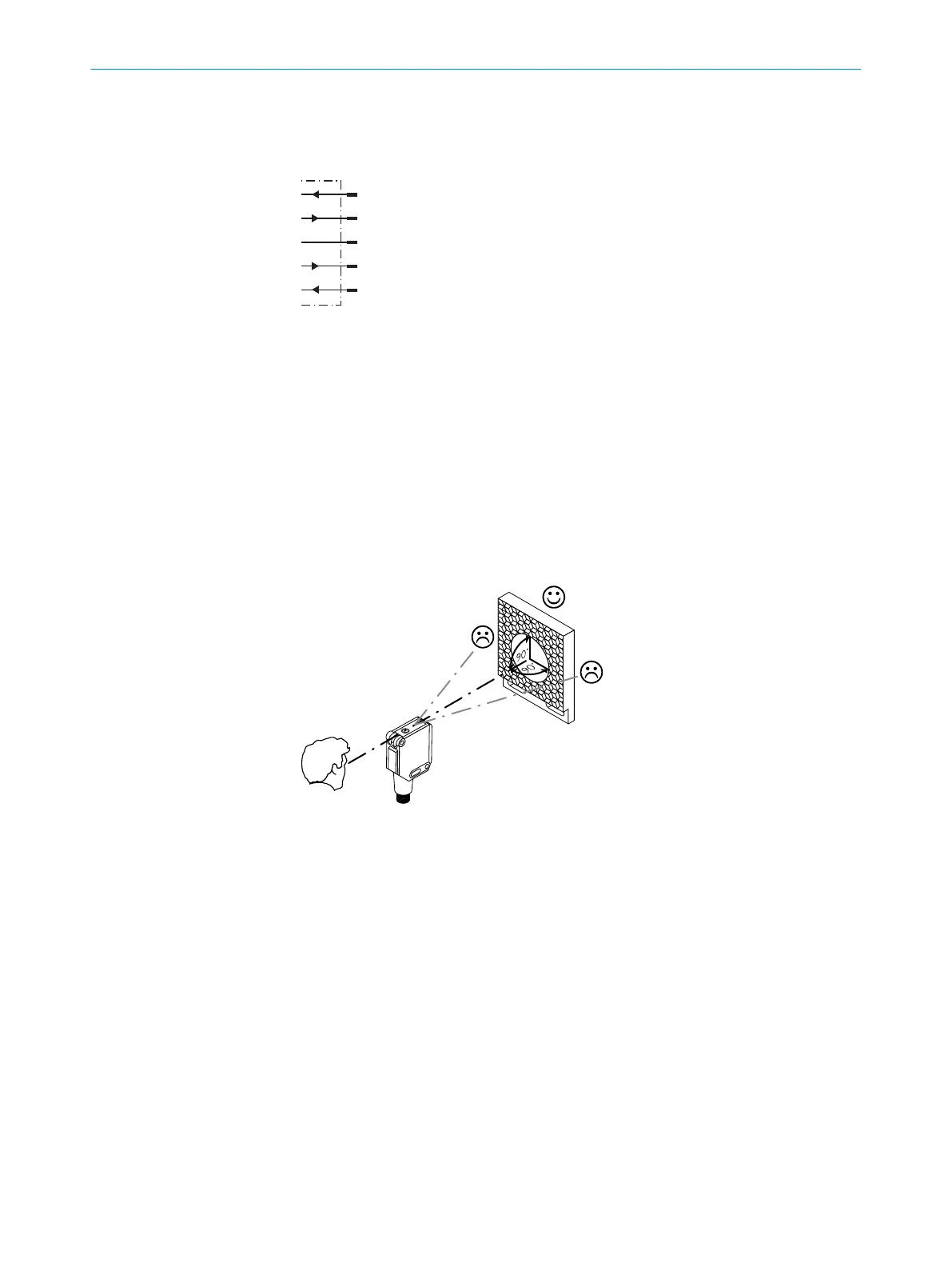
4 Align the sensor with a suitable reflector. Select the position so that the red emit‐
ted light beam hits the center of the reflector. The sensor must have a clear view of
the reflector, with no object in the path of the beam [see E]. You must ensure that
the optical openings of the sensor and reflector are completely clear. Place clear
off tape on clear foil at a distance of 60 mm between sensor and reflector.
3 COMMISSIONING
2
8016719.10DB| SICK
Subject to change without notice

 Loading...


