EasyManua.ls Logo

SICK WL34 - User Manual

SICK WL34
125 pages
Print Icon
To Next Page IconTo Next Page
Loading...
O P E R A T I N G I N S T R U C T I O N S
WL34
Compact photoelectric sensors
en, de, fr, pt, it, es, zh, ja, ru

Table of Contents

Questions and Answers

  • V
    Victoria CraigJul 29, 2025
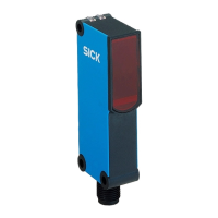
    What to do if the yellow LED flashes on my SICK WL34?
    • J
      Jonathan MartinJul 29, 2025
      If the yellow LED on your SICK Accessories is flashing, and you're seeing an alarm signal, it means the sensor is operational but not under ideal conditions. Try these steps: * Ensure the light beam is fully aligned with the reflector. * Clean the optical surfaces of both the sensor and reflector. * If the potentiometer is at maximum sensitivity, reduce the distance between the sensor and reflector and verify the reflector type. * Check if the reflector is appropriate for the application.
  • J
    Jason JacksonAug 4, 2025
    Why is the yellow LED not lighting up on my SICK Accessories?
    • D
      djohnsonAug 5, 2025
      If the yellow LED on your SICK Accessories doesn't light up, even when the light beam is aligned and there's nothing blocking it, there could be a few reasons: 1. **Voltage Issues:** Check the power supply and all electrical connections (cables and plugs) to ensure they are properly connected and providing the correct voltage. 2. **Voltage Interruptions:** Make sure the power supply is stable and free from interruptions. 3. **Faulty Sensor:** If the power supply is working correctly, the sensor itself might be defective and needs replacement.
  • N
    nicole25Aug 10, 2025
    Why is the yellow LED flashing on my SICK WL34?
    • J
      James MataAug 10, 2025
      The yellow LED flashing on your SICK Accessories indicates that the sensor is ready for operation, but the operating conditions are not ideal. You should check the following: * Align the light beam completely on the reflector. * Clean the optical surfaces of the sensor and reflector. * If the potentiometer is set to maximum sensitivity, reduce the distance between the sensor and reflector and check the reflector type. * Ensure the reflector is suitable for the application (using only SICK reflectors is recommended). * Check and adjust the sensing range if necessary. * Verify that the distance between the sensor and reflector is not too large.
  • M
    Michael ReynoldsAug 16, 2025
    What to do if the yellow LED doesn't light up on my SICK WL34 Accessories?
    • C
      christinalunaAug 16, 2025
      If the yellow LED on your SICK Accessories doesn't light up even when the light beam is aligned and there's no obstruction, it could be due to several reasons: * **No voltage or voltage below the limit values:** Check the power supply and all electrical connections (cables and plug connections). * **Voltage interruptions:** Ensure a stable power supply without interruptions. * **Faulty sensor:** If the power supply is verified as OK, consider replacing the sensor.
  • T
    Tammy BerryAug 22, 2025
    What to do if SICK WL34 has signal interruptions when object is detected?
    • S
      Sean BaxterAug 22, 2025
      If your SICK Accessories experiences signal interruptions when an object is detected, it might be due to the depolarizing property of the object's surface (e.g., tape) or reflection. Try reducing the sensitivity or changing the position of the sensor.

Summary

General Safety Notes

Safety Notes

Covers reading instructions, skilled personnel, compliance, and environmental protection.

UL Approval Notes

Correct Use of WL34 Sensor

Operating Elements and Status Indicators

Mounting

Electrical Installation

WL34-Bxxx, WL34-Vxxx

Specific electrical connection diagrams and pin assignments for WL34-Bxxx and WL34-Vxxx models.

WL34-Rxxx

Specific electrical connection diagrams and pin assignments for WL34-Rxxx models.

Additional Functions

Alarm Output

Explains the pre-failure notification output and its associated LED indicator behavior.

Test Input

How to use the test input for sender deactivation and sensor functionality verification.

Commissioning

Alignment

Proper positioning of the sensor and reflector to ensure optimal beam alignment and detection.

Sensing Range

Adjusting the sensor-reflector distance based on sensing range and operating reserve charts.

Sensitivity Setting

Using the potentiometer to adjust sensitivity for optimal performance, especially with challenging surfaces.

Time Function Setting

Configuring time delay functions (t1, t2) and relay activation for specific sensor models.

Devices with Special Features

Troubleshooting

Fault Patterns and Resolutions

Detailed troubleshooting steps for LED indicators, output signals, and environmental factors.

Disassembly and Disposal

Maintenance

Technical Data

Dimensional Drawing

Illustrations detailing the sensor's physical dimensions, mounting points, and connector placement.

SICK WL34 Specifications

General IconGeneral
Protection ClassIP 67
TypePhotoelectric Sensor
Output TypePNP
Supply Voltage10 V DC ... 30 V DC
Housing MaterialPlastic
Connection TypeConnector
Ambient Temperature Range-25°C to +55°C

Related product manuals