3
Switch: light (L) / dark
(D)
4
Switch: NPN / PNP
5
Potentiometer: adjust‐
ment of time delay t
2
6
Potentiometer: adjust‐
ment of time delay t
1
7
Potentiometer: adjust‐
ment of time stage
3
Switch: light (L) / dark
(D)
4
Switch: NPN / PNP
3
Switch: light (L) / dark
(D)
4
Potentiometer: adjust‐
ment of time delay t
2
5
Potentiometer: adjust‐
ment of time delay t
1
6
Potentiometer: adjust‐
ment of time stage
3
Switch: light (L) / dark
(D)
5 Mounting
Mount the sensor and the reflector using suitable mounting brackets (see the SICK
range of accessories). Align the sensor and reflector with each other.
Note the sensor’s maximum permissible tightening torque of 2 Nm.
6 Electrical installation
The sensors must be connected in a voltage-free state. The following information must
be observed, depending on the connection type:
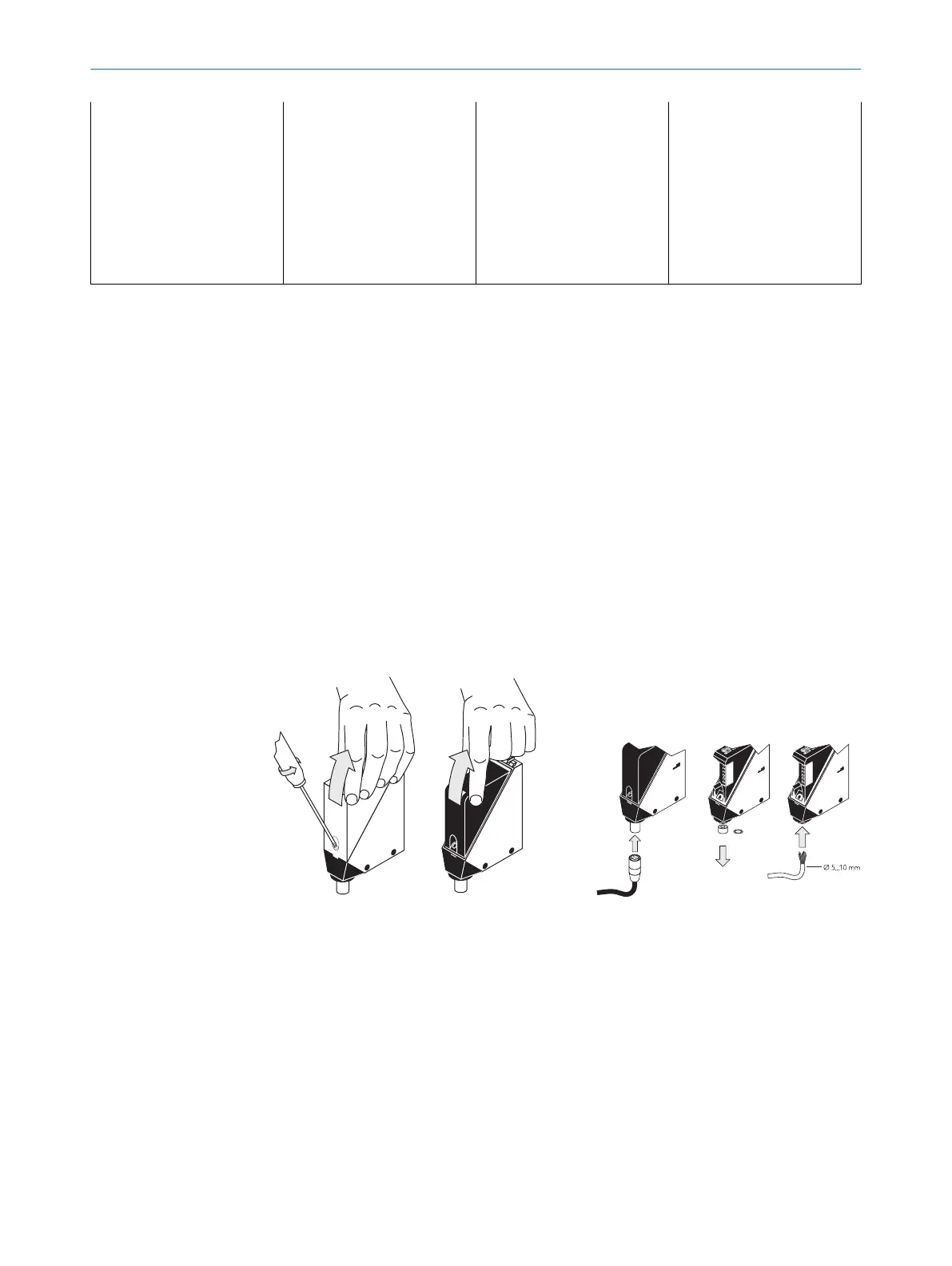
– Plug connection: note pin assignment: when the cover is open, the male connector
can be swiveled horizontally and vertically.
– Terminal connection: note the permissible cable diameter of 5 to 10 mm. When
the cover is open, the M16 fitting can be swiveled horizontally and vertically.
Unscrew the M16 fitting and remove sealing plug. Lead voltage-free supply cable
through and connect sensor in accordance with table 2 and table 4. Retighten
M16 fitting with seal so that the IP enclosure rating of the device is ensured.
Figure 1: Opening the sensor Figure 2: Electrical connection
Only apply voltage/switch on the power supply once all electrical connections have
been established.
Explanations of the connection diagram (tables, chapter 6.1 and see "WL34-Rxxx",
page 8):
Alarm = alarm output (see table 2 and Additional functions)
n. c. = not connected
NC = normally closed
NO = normally open
Q / Q = switching outputs
TE / Test = test input (see table 2 and Additional functions)
5
MOUNTING
6
8009201.11O1 | SICK
Subject to change without notice