Alarme = sortie d’alarme (voir tableau 20 et Fonctions supplémentaires)
n. c. = non connecté
NC = contact NF
NO = contact NO
Q / Q = sorties de commutation
TE/Test = entrée test (voir tableau 20 et Fonctions supplémentaires)
32.1
WL34-Bxxx, WL34-Vxxx
U
B
: 10 ... 30 V CC, voir "Caractéristiques techniques", page 40
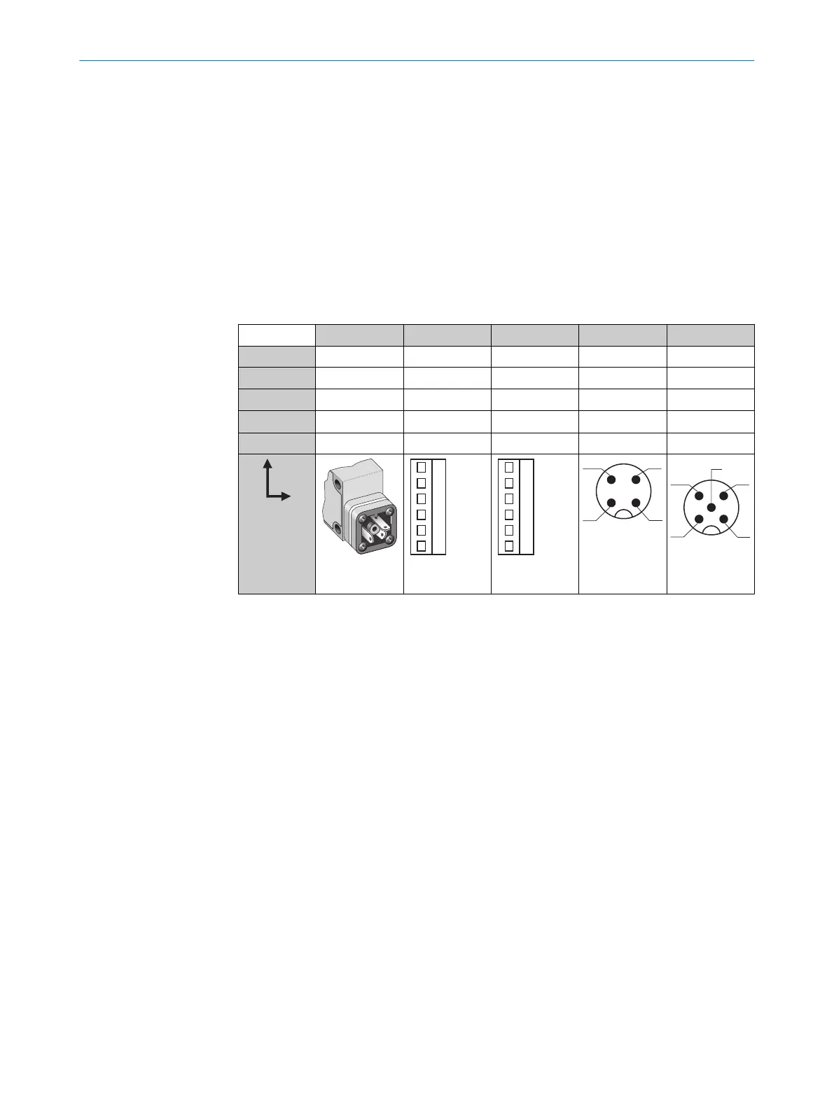
Tableau 20: CC
WL34- B3x3 B2x0 V2x0 B4x0 V5x0
1 + (L+) + (L+) + (L+) + (L+) + (L+)
2 - (M) - (M) - (M) Test Test
3
Q/Q
- Alarme - (M) - (M)
4 -
Q/Q Q/Q Q/Q Q/Q
5 - Test Test - Alarme
I
N
= 4 A
0,14 ...
1,5 mm
2
I
N
= 4 A
0,14 ...
1,5 mm
2
I
N
= 4 A
32 INSTALLATION ÉLECTRIQUE
34
8009201.11O1 | SICK
Subject to change without notice