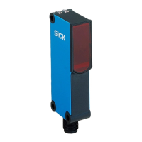
Table 6: Alarm
Alarm (≤ 100 mA)
Test input
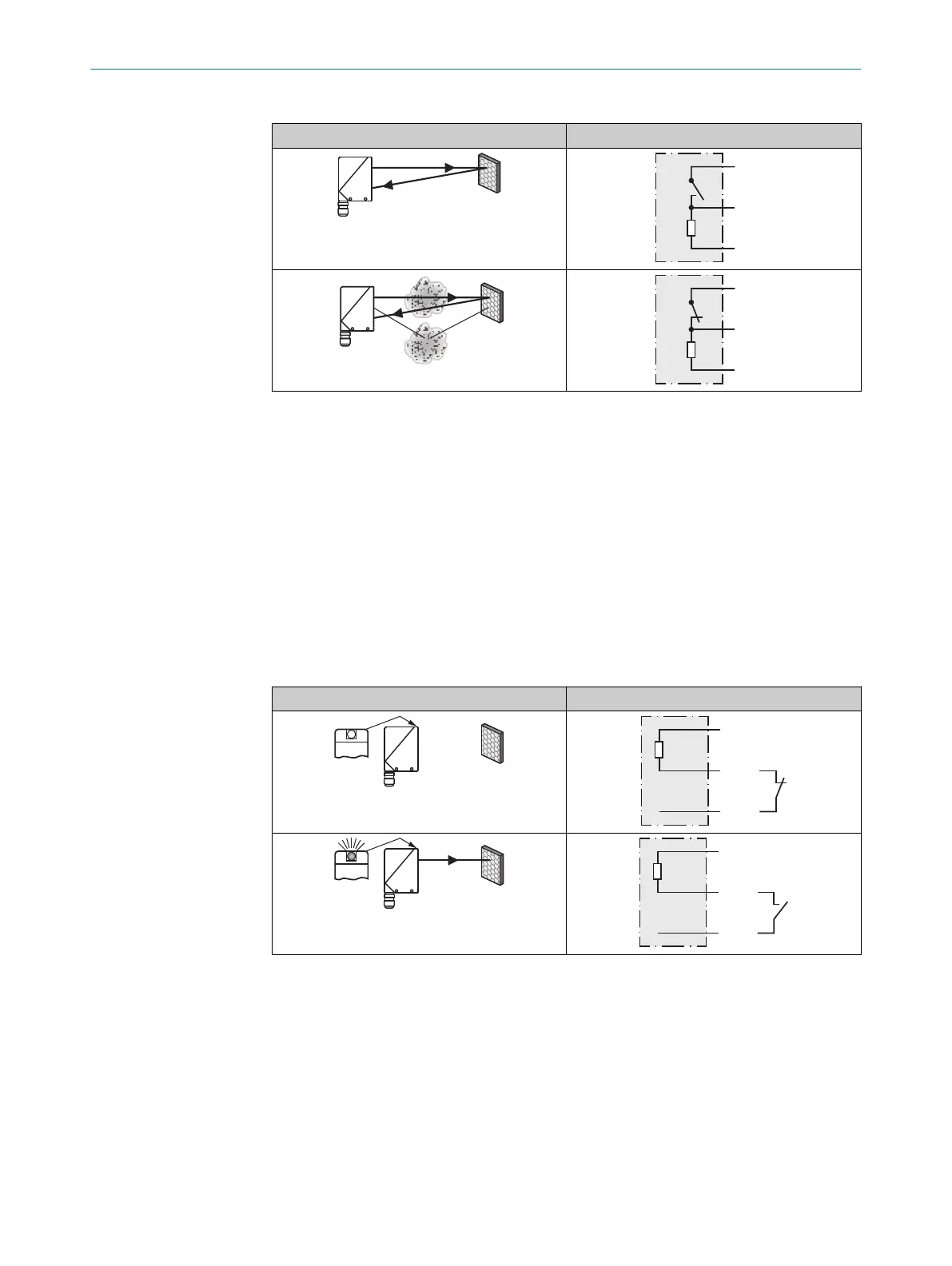
Test input: the WL34-B / -V sensors feature a test input (“TI” or “Test” on the connec‐
tion diagram [see "WL34-Bxxx, WL34-Vxxx", page 7 and see table 7]), which can be
used to switch the sender off and, therefore, check that the sensor is functioning cor‐
rectly: if female cable connectors with LED indicators are used, you have to ensure that
the TI is assigned accordingly.
There must be no object between the sensor and reflector; activate the test input (see
the connection diagram [see "WL34-Bxxx, WL34-Vxxx", page 7 and see table 7], TE at
0 V for PNP) (PNP: TE → M; NPN: TE → L+). The send LED is shut down or the detection
of an object is simulated. Use the following table to check the function. If the switching
output fails to behave in accordance with the following table, check the application con‐
ditions. See section Fault diagnosis.
Table 7: Test
Test
8 Commissioning
1 Alignment
Align the sensor with a suitable reflector. Select the position so that the red emitted light
beam hits the center of the reflector. The sensor must have a clear view of the reflector,
with no object in the path of the beam [see figure 3 and figure 4]. You must ensure that the
optical openings of the sensor and reflector are completely clear.
ADDITIONAL FUNCTIONS 7
8009201.11O1 | SICK
Subject to change without notice
9