Do you have a question about the SICK LiDAR and is the answer not in the manual?
Details the hardware integration and enabling of measurement data for 2D LIDAR sensors.
Specifies the document's inclusion with SICK part numbers and language versions.
Identifies system specialists in hardware development integrating LiDAR localization.
Explains symbols used for safety notes and instructions in the document.
Provides critical safety warnings regarding data output usage and CoLa2 for safety functions.
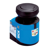
Lists supported 2D LIDAR sensors, primarily the microScan3 family, and their specifications.
Identifies the SIM1000-FXA as the controller used with LIDAR-LOC.
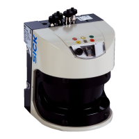
Presents a labeled overview of the microScan3 device's physical components.
Provides a labeled overview of the SIM1000 FXA controller's connections and ports.
Highlights requirements for safe integration and electrical installation, referencing operating instructions.
Details the electrical setup and connections for the microScan3 sensor.
Covers electrical installation, preparations, pin allocations, and network setup for the controller.
Emphasizes full configuration of safety functions for the 2D LIDAR sensor before data output.
Explains data output via Ethernet, UDP, and TCP/IP, referencing specific documentation.
Describes methods for activating and configuring data output via Safety Designer or CoLa2.
Details configuring data output for a single receiver using the Safety Designer tool.
Explains using broadcasting for transmitting data to multiple clients and receiver port configuration.
Explains the meaning of status LEDs on the SIM1000 FXA for operational monitoring.
| Brand | SICK |
|---|---|
| Model | LiDAR |
| Category | Accessories |
| Language | English |
