EasyManua.ls Logo

SICK DT80 IO-Link - User Manual

SICK DT80 IO-Link
46 pages
Print Icon
To Next Page IconTo Next Page
Loading...
O P E R A T I N G I N S T R U C T I O N S
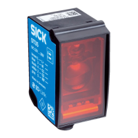
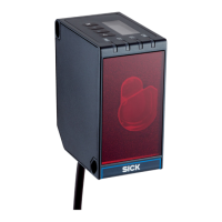
DT80 IO-Link
Distance sensor

Table of Contents

Questions and Answers

  • E
    edwardstuartAug 14, 2025
    How to troubleshoot SICK Accessories when no measurement is displayed?
    • L
      lawrenceburkeAug 14, 2025
      If your SICK Accessories device isn't displaying measurements, it could be due to several reasons. First, ensure the measuring laser is activated. Next, verify that the laser light spot is correctly aimed at the object. Also, confirm that the light path is clear and the object is within the measuring range. Finally, make sure the receiver element is receiving enough light and check the surface condition if reflective surfaces are present.
  • C
    Cathy KingAug 18, 2025
    Why does SICK Accessories measurement data show anomalies?
    • D
      danielle32Aug 18, 2025
      If your SICK Accessories device is showing measurement data anomalies, the viewing window might be contaminated. Clean the viewing window to resolve this issue.
  • D
    Derek HernandezAug 21, 2025
    What to do if SICK Accessories is in an EMC disturbed environment?
    • C
      Christopher LongAug 21, 2025
      If your SICK Accessories device is being operated in an EMC disturbed environment, use data output via IO-Link. If measured values must be output via the analog output, use an analog current output because it is significantly less susceptible to electromagnetic interference than a voltage output.
  • T
    Travis RodgersAug 25, 2025
    What does error code 0x020100FF mean on SICK DT80 IO-Link?
    • L
      Laura OlsonAug 25, 2025
      If error code 0x020100FF appears on your SICK Accessories device, increase the reflectivity of the measuring object or reduce the measuring distance.
  • C
    Charles BookerAug 27, 2025
    How to turn on the measuring laser on SICK DT80 IO-Link?
    • C
      Caitlin HernandezAug 27, 2025
      To ensure the measuring laser is switched on, verify the laser is enabled in the device settings.
  • J
    Jesus ElliottAug 31, 2025
    What does error code 0x02010100 mean on SICK Accessories?
    • W
      wrojasAug 31, 2025
      If error code 0x02010100 appears on your SICK Accessories device, reduce the reflectivity of the measuring object or increase the measuring distance.
  • T
    Tammy GarciaSep 3, 2025
    How to troubleshoot SICK Security Sensors not displaying measurements?
    • S
      Shawn LopezSep 3, 2025
      If your SICK Security Sensor isn't displaying measurements, it could be due to several reasons. First, ensure the measuring laser is activated. If it is, check the device alignment to ensure the laser light spot is aimed correctly. Also, confirm that the light path is clear and the object is within the sensor's measuring range. Ensure that the receiver element of the device is receiving enough light. Finally, reflective surfaces can cause issues, so check the surface condition of the object being measured.
  • K
    Karen PughSep 6, 2025
    How to turn on measuring laser on SICK Security Sensors?
    • L
      Lindsey BensonSep 7, 2025
      If the measuring laser is switched off, ensure the laser is switched on in the device settings.
  • P
    Peter PetersonSep 12, 2025
    How to prevent EMC disturbance in SICK Security Sensors?
    • D
      Deborah FullerSep 12, 2025
      To mitigate EMC disturbances when operating your SICK Security Sensor, use data output via IO-Link. If measured values must be output via the analog output, use an analog current output, as it is significantly less susceptible to electromagnetic interference than a voltage output.

Summary

DT80 IO-Link Operating Instructions

Product Overview

Introduction to the DT80 IO-Link as a distance sensor.

Product and Manufacturer Information

Described Product Variants

Details on product variants with IO-Link and Ethernet interfaces, manufacturer, and legal information.

About This Document

Document Structure and Conventions

Explains document usage, target audience, further information, and symbol conventions.

Safety Information

Intended Use, Hazards, and Personnel

Covers intended use, improper use, cybersecurity, personnel qualification, and operational hazards.

Device Warning Symbols and Laser Safety

Details warning signs on the device, focusing on laser safety classifications and precautions.

Product Description

Product Identification and Type Label

Explains how to identify the product using SICK ID and the type label details.

IO-Link Interface and Delivery Scope

Details the IO-Link interface, supported functions, documentation, accessories, and scope of delivery.

Status Indicators and Operating Elements

Overview of the device's status LEDs, display, and operating buttons.

Transport and Storage

Handling and Storage Procedures

Guidelines for safe transport, unpacking, inspection, and proper storage conditions.

Mounting

Mounting Site and Instructions

Recommendations for selecting a mounting site and general mounting instructions.

Device Mounting Process

Step-by-step guide for physically attaching and aligning the sensor.

Electrical Installation

Wiring Instructions and Electrical Connection

Detailed instructions for wiring, connection diagrams, and electrical hookup.

IO-Link Integration

How to integrate the sensor into an IO-Link network and master system.

Operation

General Operation and Status Indicators

General operating principles, notes on handling, and explanation of status LEDs.

User Interface: Display and Buttons

Description of the device's TFT display, RUN mode, and the function of the operating buttons.

Device Menu and Configuration Software

Main Menu and Quick Setup

Overview of the main menu structure and quick setup options for cycle time.

SOPAS ET Configuration Tool

Guidance on using the SOPAS ET software for parameterization and diagnostics.

IO-Link Operation

Computer-Based Parameterization via SOPAS ET

Steps for parameterizing the device using SOPAS ET and a SiLink master.

IO-Link Interface Properties

Key technical properties of the device's IO-Link interface, including specification and cycle time.

IO-Link Configuration and Process Data

IO-Link Configuration Methods

How to configure the sensor via IO-Link using SiLink box or IO-Link Master.

Process Data Formats and Configuration

Details on available process data formats and how to configure them.

Device Operation and Setup Parameters

Device Data and IO-Link Access

Transmitting device data and accessing it via IO-Link using IODD.

Manual Setup: Cycle Time and Distance Offset

Configuring measurement cycle time and setting a distance offset value.

Advanced Manual Setup Options

Measured Value Filtering and Echo Behavior

Configuring measured value filters and handling 'no echo' situations.

Display Brightness and Laser Control

Adjusting display brightness and controlling the measuring laser.

Device Settings and Output Logic

Factory Reset and Output State Logic

Procedures for factory reset and configuring the active state logic for outputs.

Hysteresis and Output Q1 Modes

Setting hysteresis for stable switching and configuring Output Q1 modes.

Q1 Output Switching Configuration

Single Point Switching for Q1

Configuring a single switching point for the Q1 digital output.

Window Switching for Q1 Output

Setting up a switching window with SP1 and SP2 for the Q1 digital output.

Q1 Offset and Q2 Output Configuration

Q1 SP +;- Offset Configuration

Setting Output Q1 using a switching point with an offset reference.

Q2 Analog Output (Current;Voltage)

Configuring Output Q2 as an analog current (4-20mA) or voltage (0-10V) output.

Q2 Output Functions

Analog Output Functions for Q2

Details on 4-20 mA current and 0-10 V voltage output functions for Q2.

Q2 Digital Output Modes

Configuration of Q2 as a digital output with modes like Single-point, Alarm, SLW, etc.

Input and Advanced Output Functions

Q2 Alarm, SLW, and Complementary Outputs

Configuring Q2 for alarm signals, signal level warnings, and complementary output functions.

Input In1 Configuration and Sender Control

Setting up the In1 input and controlling the measuring laser via input or software.

Device Presets and Other Functions

Distance Preset Functionality

Setting custom initialization values for distance output via preset.

Device Information and Find Device Function

Accessing device info (HW/SW versions) and using the Find device function.

Maintenance

Cleaning the Device

Guidelines for cleaning the front screen and housing, including safety precautions.

Maintenance Schedule and Tasks

Recommended preventive maintenance tasks, intervals, and responsibilities.

Troubleshooting

General Faults and Troubleshooting Guide

Table of common problems, causes, and corrective actions for device operation.

Error Detection and Memory

How the device detects, displays, and stores internal error states.

Error Codes, Repair, Return, and Disposal

Specific Error Codes and Solutions

Detailed list of error codes, their meanings, and specific remedial actions.

Repair, Return, and Disposal Procedures

Guidelines for device repair, return process, and environmentally sound disposal.

Deinstallation and Data Storage

Sensor Replacement and Data Backup

Using IO-Link Data Storage for parameter backup and restoration during sensor replacement.

Technical Data

Performance Specifications

Key performance metrics like measuring range, resolution, repeatability, and accuracy.

Response Time Variations

Table detailing response times based on output time settings and object/filter dependencies.

Interface Specifications

General Interface Capabilities

Details on digital output, analog output, and digital input interfaces supported by the device.

IO-Link Communication Technical Data

Technical specifications for the IO-Link interface, including max cable length.

Mechanics, Electronics, and Environmental Data

Mechanical and Electrical Specifications

Specifications for supply voltage, power consumption, housing, dimensions, and display.

Environmental and Operational Conditions

Data on vibration resistance, shock resistance, ambient light immunity, and temperature limits.

Dimensional Drawing

Device Dimensions and Optical Axes

Visual representation of device dimensions, mounting points, and optical axis locations.

Accessories

Accessory Information and Product Page

Information on how to find available accessories and related installation details.

Annex and Compliance Information

Conformity and Certificates

Information on obtaining product conformity declarations and certificates from the manufacturer.

Software Licenses

Details regarding the open-source software licenses used within the product.

SICK DT80 IO-Link Specifications

General IconGeneral
Communication InterfaceIO-Link
Enclosure ratingIP67
Supply voltage18 V DC ... 30 V DC
Ambient temperature-10 °C ... +50 °C
Weight (approximate)100 g
Operating Temperature-10 °C ... +50 °C
Product categoryDistance sensors
Light sourceRed LED
AdjustmentTeach-in
Output typeDigital, Analog
Digital output1 PNP
Analog output4-20 mA / 0-10 V
Housing materialABS
Connection typeConnector M12, 5-pin
Weight100 g
Operating voltage18 V DC ... 30 V DC
ConnectionConnector M12, 5-pin

Related product manuals