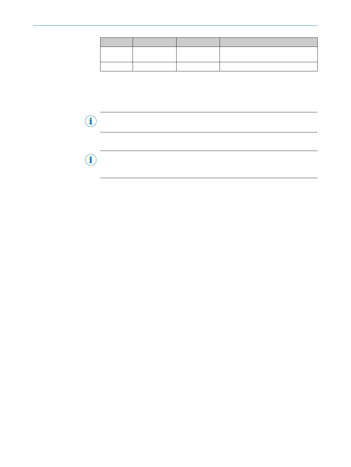
Contact Signs Wire color Description
4 Q
1
/C Black Output 1: Digital output1(push-pull
stage)/IO-Link
5 In1 Gray Input 1: Digital input
6.3 Integration of the sensor in IO-Link mode
To operate the product in IO-Link mode, it must be connected to a suitable IO-Link
Master. This is used for further integration into the control system.
NOTE
The cable length between the IO-Link Master and IO-Link device: maximum 20m.
Details on integration can be found in the detailed IO-Link description.
NOTE
After successful connection of the product to the IO-Link Master, the green LNK LED
flashes to indicate a functioning IO-Link communication between the master and device.
6 ELECTRICAL INSTALLATION
18
O P E R A T I N G I N S T R U C T I O N S | DT80 IO-Link 8028220.1N23/2024-05-24 | SICK
Subject to change without notice

 Loading...


