6 Electrical installation
6.1 Wiring instructions
NOTE
Pre-assembled cables can be found on the product page.
It can be accessed via the SICK ProductID: pid.sick.com/{P/N}/{S/N}
{P/N} corresponds to the part number of the product, see type label.
{S/N} corresponds to the serial number of the product, see type label (if specified).
NOTICE
Faults during operation and defects in the device or the system
Incorrect wiring may result in operational faults and defects.
■
Follow the wiring notes precisely.
Use IO-Link standard cables for the specified ambient temperature range.
The enclosure rating stated in the technical data is achieved only with screwed plug
connectors or protective caps.
After disconnecting the device from the voltage supply, wait 4seconds before recon‐
necting the voltage supply.
6.2 Connecting the device electrically
NOTICE
All electrical circuits must be connected to the device with safety or protective extra-low
voltage (SELV or PELV).
1. Ensure the voltage supply is not connected.
2. Connect the sensor as per the connection diagram.
3. Observe the wiring instructions, see "Wiring instructions", page 17.
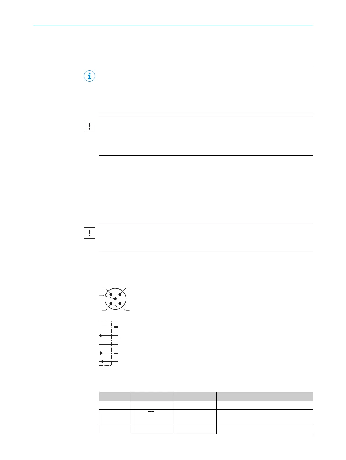
L+
1
brn
M
3
blu
Q1/C
4
blk
QA/Q2/
¯
Q1/–
2
wht
In1
5
gra
Figure 6: Connection diagram, 5-pin male connector
Table 3: Legend for connection diagram
Contact Signs Wire color Description
1 L+ Brown Supply voltage
2 Q
A
/Q
2
/Q
1
/- White Output 2: Analog output/digital output2
(push-pull stage)
3 M Blue Supply voltage 0V
ELECTRICAL INSTALLATION 6
8028220.1N23/2024-05-24 | SICK O P E R A T I N G I N S T R U C T I O N S | DT80 IO-Link
17
Subject to change without notice

 Loading...


