Parameter Values Factory setting
Teach In SP2 or Edit SP2
value
50mm…80,000mm 5,000mm
Hysteresis 0mm…80,000mm 2mm
When teaching in the switching points (Teach In), the following applies: Regardless of
SP1 and SP2, the greater distance serves as the remote switching point and the closer
distance serves as the near switching point for the active window area (regardless of
HIGH active or LOW -active). If no measurement is possible (e.g., the object is in the
blind spot of the device, the remission factor is too low, or the light reflection is too
low), Window output mode outputs a switching signal that corresponds to the expected
behavior at the maximum distance. When changing between Window and Single point
switching modes, it is possible for the previously selected logic setting and/or the
switching point setting to change.
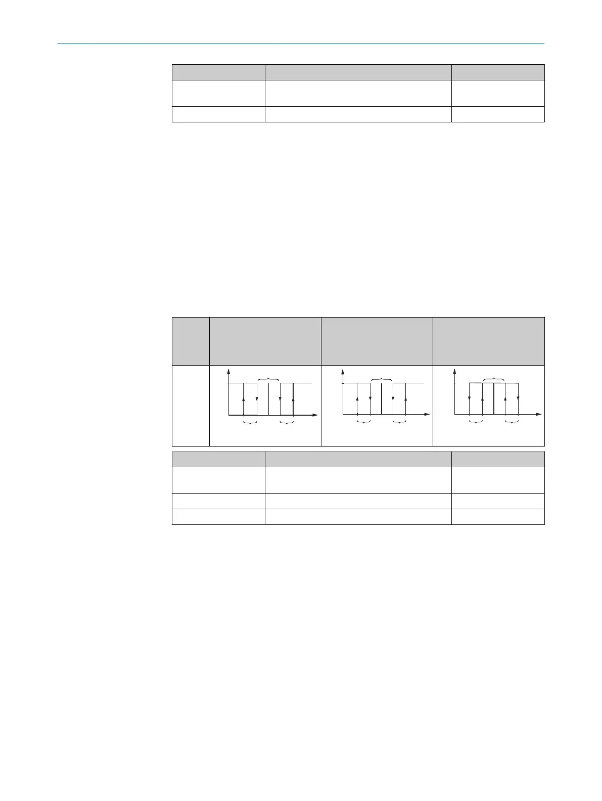
7.6.10.4 Q1 SP +/- offset (switching point +/- offset)
Sets a background (switching point) as the reference. The output state is active when
the distance output value is within the tolerance around the switching point.
Table 12: Q1 SP +/- offset (switching point +/- offset)
Switch‐
ing
func‐
tion
Output state Electrical voltage at Q
i
for
active state = High
Electrical voltage at Q
i
for
active state = Low
Switch‐
ing win‐
dow for
refer‐
ence
back‐
ground
Inaktiv
Aktiv
SP1
Hysterese
Ausgabewert
Objektge-
schwindigleit
Schalt-
zustand
Hysterese
Toleranz um den Schaltpunkt
SP1
Hysterese
Ausgabewert
Objektge-
schwindigleit
Hysterese
Spannung
High
Low
Toleranz um den Schaltpunkt
SP1
Hysterese
Ausgabewert
Objektge-
schwindigleit
Hysterese
Spannung
High
Low
Toleranz um den Schaltpunkt
Parameter Values Factory setting
Teach In SP or Edit SP
value
50mm … 80,000mm 1,000mm
Edit offset value 0mm … 80,000mm 40mm
Hysteresis 0mm … 80,000mm 2mm
If no measurement is possible (e.g., the object is in the blind spot of the device, the
remission factor is too low, or the light reflection is too low), SP +/- offset output mode
outputs a switching signal that corresponds to the expected behavior at the maximum
distance. When changing between the SP +/- offset and Window switching modes, it is
possible for the previously selected logic setting and/or the switching point setting to
change.
7.6.11 Interface > Output Q2 (Output Q2/Qa)
The Q2/Qa output can be configured either as an analog output or as a digital
output. When an output mode is selected, the desired settings can be taught in or set
manually.
7.6.11.1 Q2 Analog (analog output)
Current (current output)
Output Q2 is an analog current output. The measured value is output in the form of a
linear current value.
7 OPERATION
28
O P E R A T I N G I N S T R U C T I O N S | DT80 IO-Link 8028220.1N23/2024-05-24 | SICK
Subject to change without notice

 Loading...


