Table 4: Meaning of the indicator lights
LED Display Meaning
LNK
O
(green)
Connection to the IO-Link Master
established
Ö
(green) irregular
IO-Link data connection for data
transmission
Ö
(green) regular
Find device mode active
o
Off
No IO-Link data connection
Q2
O
(yellow)
Digital output high or measured value
within the scaling range for the ana‐
log output
o
Off
Digital output low or measured value
outside the scaling range for the ana‐
log output
Q1
O
(yellow)
Digital output high
o
Off
Digital output low
Q2and Q1
ÖÖ
(yellow) simultaneously for approx.
3s
Teach-in operation (Teach-in) in prog‐
ress
ÖÖ
(yellow) alternately for approx. 5s
Teach-in operation has failed
PWR
O
(green)
Device ready for operation
o
Off
No voltage supply
Ö
(red)
Device error, see "Detecting and dis‐
playing errors", page 34
O = Lights up; Ö = Flashes; o = Does not light up.
7.3 Operation via pushbuttons and display
7.3.1 Display and operating buttons
Display
The device has a full-color TFT display that shows measurement and diagnostic data
and can be used to parameterize the device.
After switching on the device, the display is in RUN mode. Press the “Down” pushbutton
and switch between the following displays:
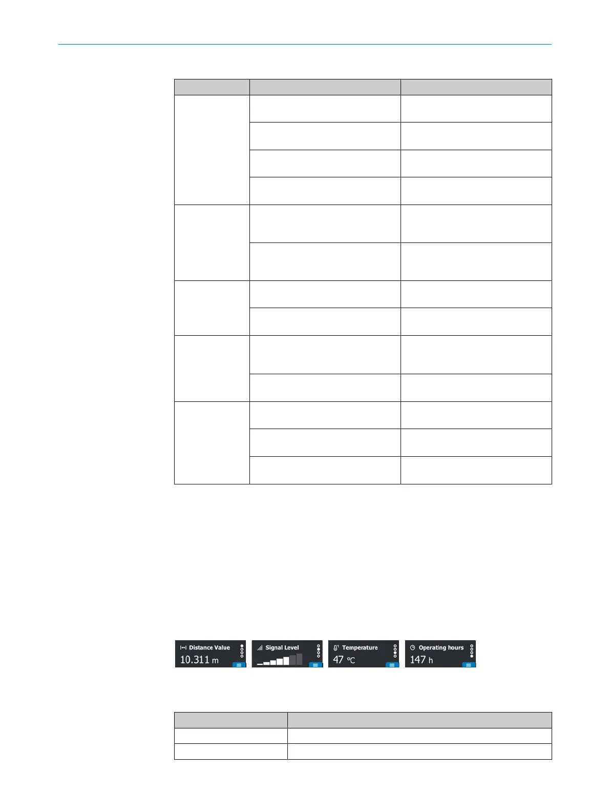
Figure 7: Display in RUN mode
Table 5: Displays in RUN mode
Display Description
Distance Value Measured distance in meters
Signal level Signal strength as bar graph
7 OPERATION
20
O P E R A T I N G I N S T R U C T I O N S | DT80 IO-Link 8028220.1N23/2024-05-24 | SICK
Subject to change without notice

 Loading...


