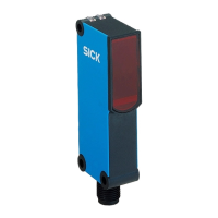
Figure 3: Alignment Figure 4: Alignment 2
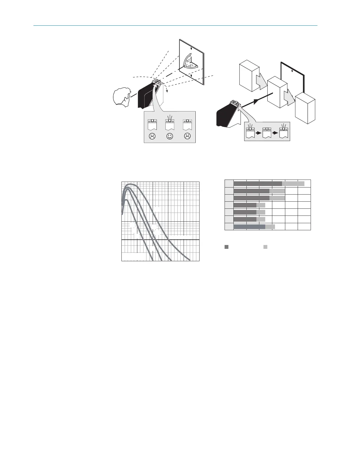
2 Sensing range
Adjust the distance between the sensor and the reflector according to the corresponding
diagram [see following figure] (x = sensing range, y = operating reserve).
100
10
1
Sensing range
Sensing range
typ. max.
m
(feet)
5
(16.40)
10
(32.81)
15
(49.21)
20
(65.62)
25
(82.02)
Distance in m (feet)
1
2
3
4
5
6
7
Figure 5: characteristic curve
0
4
(13.12)
8
(26.25)
12
(39.37)
16
(52.49)
20
(65.62)
24
(78.74)
5
6
4
3
2
1
Distance in m (feet)
Sensing range
11 16
15 22
Sensing range max.
7
10
0.03
7
14 20
11 160.03
0.03
0.03
10
13
0.15
7
10
0.03
7
10
0.03
1
Reflector PL80A
2
Reflector PL50A
3
Reflector PL40A
4
Reflector PL30A
5
Reflector PL20A
6
Diamond Grade reflective tape
7
Reflector C110A
3 Sensitivity setting
Sensor with potentiometer: open the sensor cover and protective hood, make sure that no
dirt has gotten into the device.
The sensitivity is adjusted with the potentiometer (type: without stop). Clockwise rotation:
operating reserve increased; counterclockwise rotation: operating reserve reduced. We rec‐
ommend setting the potentiometer to “Maximum”. A lower operating reserve may be nec‐
essary for depolarizing surfaces.
The sensor is adjusted and ready for operation.
4 Time function setting
WL34xx4x: no time delay, t1 = time delay, t2 = time delay; for -R: 0 = relay deactivated, 1 =
relay active. Time delay selector switch can be set on the device according to the following
graphic.
Time stages: 0.5 ... 10 s can be adjusted.
8 COMMISSIONING
10
8009201.11O1 | SICK
Subject to change without notice