0
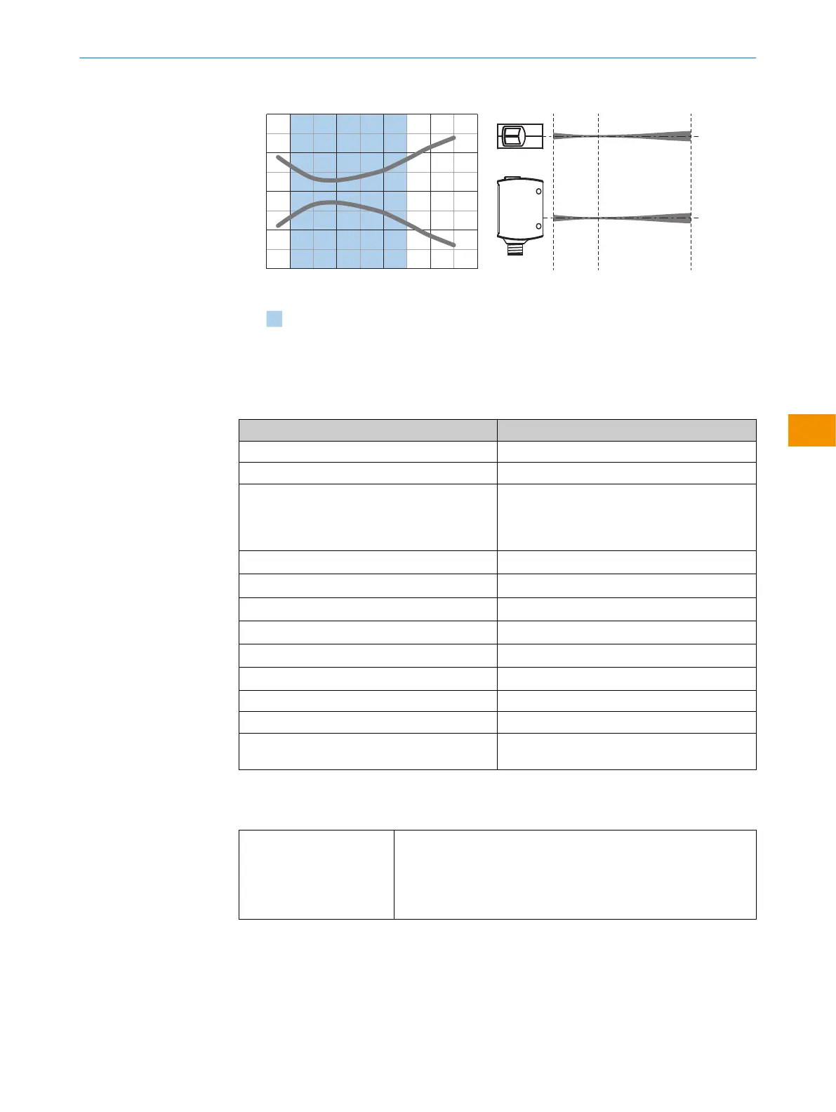
Abstand in mm
Abmessungen in mm
0,4
0,8
–0,8
–0,4
0
Empfohlener Schaltabstandsbereich für
beste Performance
45035025015050 40025 150
Abbildung 27: Lichtfleckdiagramm, Short Range
11.4 Prozessdatenstruktur
WTx10 A00
IO-Link V1.1
Prozessdaten 4Byte
Byte 0: Bits 24 ... 31
Byte 1: Bits 16 ... 23
Byte 2: Bits 8 ... 15
Byte 3: Bits 0 ... 7
Bit0/Datentyp Q
L1
/Boolesch
Bit1/Datentyp Q
L2
/Boolesch
Bit2/Datentyp Q
Int1
Bit3/Datentyp Q
Int2
Bit4/Datentyp Q
Int3
Bit5/Datentyp Q
Int4
Bit6/Datentyp Betriebszustand Sensor
Bit 7 ... 15/Datentyp [leer]
Bit 16 ... 31/Datentyp Ganzzahliger Abstand ohne Vorzeichen (ganze
mm-Werte)
12 Glossar
ApplicationSelect The ApplicationSelect function is available for sensors with the Multi‐
Mode function.
Selecting ApplicationSelect increases the sensing range of the sen‐
sor and the sensitivity rises so that even shiny, dark and uneven
objects, even in an inclined position, are safely detected.
BETRIEBSANLEITUNG
9382969/2024-02-23 | SICK B E T R I E B S A N L E I T U N G | WTM10L
33
Irrtümer und Änderungen vorbehalten
de