St art-Stop Push Button A1 49SAP05
For-Rev-Stop Push Button A2 49SAP02
High-Low-Stop A2 49SAP03
H-O-A Selector Switch A3 49SAS 01
OFF/ON Selector Switch A4 49SAS04
For-Off-Rev Selector Switch A5 49SAS02
High-Off-Low Selector Switch A5 49SAS03
Keyed H-O-A Selector Switc h A9 49SAS09
Pilot Light Kit Voltages:
E-600V, F-120V, G-240V,
H-480V, J-24V
Pilot Light R ed “ON” FA
49SPL0BR(E,F,G,H,J)
49SPL0BG(E,F,G,H,J)
49SPL0CG(E,F,G,H,J)
49SPL0CR(E,F,G,H,J)
49SPL0AG(E,F,G,H,J)
49SPLPBG(E,F,G,H,J)
49SPL0AR(E,F,G,H,J)
49SPLPBR(E,F,G,H,J)
Pilot Light Green “ON” FB
Pilot Light R ed “Run” FC
Pilot Light Green “Run” FD
Pilot Light R ed “ Off”
F J
Pilot Light Green “ Off” FK
Push-to-Test Red “ ON” FS
Push-to-Test Green “ ON” FT
Push-to-Test Green “ Off”
Pilot Light White “Control Power On”
OL Relay Trip Alarm Light - Amber
FL
Control Power Transformers
St andard Capacity: Sizes 0 - 2.5
Sizes 3 - 3.5 Size 4
208/120V KTH050 KTH100 KTH150
208/24V KTG050 KTG100 KTG150
240/120V KT8050 KT8100 KT8150
277/120V KT7050 KT7100 KT7150
277/24V KT5050 KT5100 KT5150
480/120V KT8050 KT8100 KT8150
480/24V KT4050 KT4100 KT4150
600/120V KT9050 KT9100 KT9150
600/24V KT6050 KT6100 KT6150
KT_ _ 50 is 45VA (primary fusing not required)
KT_ _ 100 is 100VA (with primary fusing)
KT_ _ 150 is 150VA (with primary fusing)
E. Motor Starter or Contactor
See device label for appropriate replacement parts sheet.
F. Auxiliary Contacts - Not Shown
Auxiliary
Contacts
(Inst alled on
contactor)
1NO G10 1-49AB10
2NO G20 1-49AB20
3NO G30 1-49AB20 + 1-49AB10
4NO G40 1-49AB40
1NC G01 1-49AB01
2NC G02 2-49AB01
1NO & 1NC G11 1-49AB11
1NO & 2NC G12 1-49AB12
2NO & 1NC G21 1-49AB21
2NO & 2NC G22 1-49AB22
2NO & 1NC G31 1-49AB31
Disconnect switch interlock 2NO/2NC
30 - 200A GY HA261234
Ground Lug 3-Conductor L10 75D28182001
120V Coil Transient Suppressor - Per Coil SS 49D26344
Relay 2NO & 2NC (120V) R22 3RH2122-1AK60
Relay 4NO (120V) R40 3RH2140-1AK60
Relay 4NC (120V) R04 3RH2122-1AK60
Factory
Suffix
Field
Kit
G. Control Options - Not Shown
Factory
Suffix
Field
Kit
Control Options
Factory
Suffix
Field
Kit
Control Relays
D. Control Power Transformers
Pilot Lights
Factory
Suffix
Field
Kit
Factory
Suffix
Field
Kit
Push Buttons/
Selector Switches
C. Pilot Devices
Replacement Parts
49SPLPAG(E,F,G,H,J)
49SPL0DW(E,F,G,H,J)
49SPL0EA(E,F,G,H,J)
FU
FW
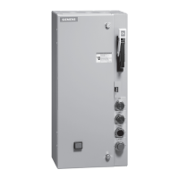
Replacement Parts and Instruction Guide
E87010-A0137-T003-A4
Siemens Industry, Inc. 3617 Parkway Ln, Peachtree Corners, GA 30092 www.usa.siemens.com 3 A5E31166526A-003
H. Quarter-Turn Latch
Enclosure Type Catalog Number
1, 3R, 12 75D46260004
4, 4X 75D46260005
J. Overload Relay Reset Operator
Enclosure Type Catalog Number
1 49MBRS1
3R, 4, 4X, 12 49MBRS2