EasyManua.ls Logo

Siemens 17 - User Manual

Siemens 17
6 pages
Print Icon
To Next Page IconTo Next Page
Loading...
IMPORTANT
THESE INSTRUCTIONS DO NOT PURPORT TO COVER ALL DETAILS OR VARIATIONS IN
EQUIPMENT, NOR TO PROVIDE FOR EVERY POSSIBLE CONTINGENCY TO BE MET IN
CONNECTION WITH INSTALLATION, OPERATION OR MAINTENANCE. SHOULD
FURTHER INFORMATION BE DESIRED OR SHOULD PARTICULAR PROBLEMS ARISE
WHICH ARE NOT COVERED SUFFICIENTLY FOR THE PURCHASER’S PURPOSES, THE
MATTER SHOULD BE REFERRED TO THE LOCAL SIEMENS SALES OFFICE.
THE CONTENTS OF THIS INSTRUCTION MANUAL SHALL NOT BECOME PART OF OR
MODIFY ANY PRIOR OR EXISTING AGREEMENT, COMMITMENT OR RELATIONSHIP.
THE SALES CONTRACT CONTAINS THE ENTIRE OBLIGATION OF SIEMENS. THE
WARRANTY CONTAINED IN THE CONTRACT BETWEEN PARTIES IS THE SOLE
WARRANTY OF SIEMENS. ANY STATEMENTS CONTAINED HEREIN DO NOT CREATE
NEW WARRANTIES OR MODIFY THE EXISTING WARRANTY
.
Combination Starters, Classes 17, 18, 25, 26 and 32
Starter Sizes 0 - 4
Replacement Parts and Instruction Guide
E87010-A0137-T003-A4
August 2020
Supersedes Issue of
June 2015
Siemens Industry, Inc. 3617 Parkway Ln, Peachtree Corners, GA 30092 www.usa.siemens.com A5E31166526A-003
Hazardous voltage.
Will cause death, serious personal injury,
or property damage.
SIGNAL WORDS
The signal words “Danger”,“Warning” and “Caution”
used in this manual indicate the degree of hazard that
may be encountered by the user.
These words are defined as below:
Danger - Indicates death, severe personal injury or
property damage will result if proper
precautions are not taken.
Warning - Indicates death, severe personal injury, or
property damage can result if proper
precautions are not taken.
Caution - Indicates personal injury or property
damage may result if proper precautions
are not taken.
Short-Circuit Explosion Hazard. Can cause death, serious
personal injury, or property damage. Fully engage all
door latches and spread ends of door hinge pins
approximately 45 degrees before energizing equipment.
QUALIFIED PERSON
For the purpose of this manual and product labels a
qualified person is one who is familiar with the installa-
tion, construction, operation, or maintenance of the
equipment and the hazards involved. In addition this
person has the following qualifications:
(a) is trained and authorized to energize,
de-energize, clear, ground, and tag circuits
and equipment in accordance with established
safety practices.
(b) is trained in the proper care and use of
protective equipment such as rubber gloves,
hard hat, safety glasses or face shields, flash
clothing, etc., in accordance with established
safety practices.
(c) is trained in rendering first aid.
Always de-energize and ground the equipment before
maintenance. Read and understand this manual before
installing, operating or maintaining the equipment.
Maintenance should be performed only by qualified
personnel. The use of unauthorized parts in the repair of
the equipment or tampering by unqualified personnel may
result in dangerous conditions which may cause death or
serious personal injury or equipment or property damage.
Follow all safety instructions contained herein.
s
Question and Answer IconNeed help?

Do you have a question about the Siemens 17 and is the answer not in the manual?

Summary

Safety and Signal Words

Signal Words Definitions

Defines hazard signal words like Danger, Warning, and Caution used in the manual.

Qualified Person Requirements

Specifies the training and authorization required for personnel handling the equipment.

Replacement Parts - Disconnects and Breakers

Disconnect Switch Type Selection

Lists disconnect switch types, with and without fuse clips, and their catalog numbers.

Handle Replacement Instructions

Circuit Breaker Handle Replacement

Circuit Breaker Handle Installation

Circuit Breaker Assembly Instructions

Instructions for ensuring correct installation and functionality of the circuit breaker handle.

Overview

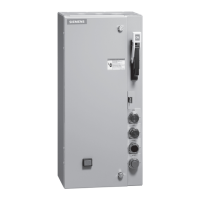
This document outlines the replacement parts and instruction guide for Siemens Combination Starters, Classes 17, 18, 25, 26, and 32, covering starter sizes 0-4. It serves as a comprehensive resource for understanding the device's components, operational procedures, and maintenance requirements.

Function Description

The Siemens Combination Starter is an integrated electrical control device designed to provide motor starting, stopping, and overload protection within a single enclosure. It combines a disconnect means (either a disconnect switch or a circuit breaker) with a motor starter (contactor and overload relay). This integration simplifies wiring, reduces installation space, and enhances safety by providing a single point of control and disconnection for the motor circuit. The various classes (17, 18, 25, 26, 32) and sizes (0-4) indicate different configurations and capacities, catering to a wide range of motor control applications. The disconnect switch or circuit breaker provides the means to safely isolate the motor circuit from the main power supply for maintenance or emergency situations. The motor starter, comprising a contactor and an overload relay, is responsible for switching the motor on and off and protecting it from excessive current draw that could lead to overheating and damage.

Usage Features

The combination starter is designed for ease of use and robust operation in industrial environments. Key features include:

  • Integrated Control: By combining the disconnect and motor starter functions, the device offers a streamlined control solution. Operators can manage motor operation and safety from a single point, reducing complexity.
  • Disconnect Options: Users can select between a disconnect switch (with or without fuse clips) or a circuit breaker as the primary disconnect means. This flexibility allows for tailoring the protection scheme to specific application requirements, such as the need for fuse protection or the convenience of a resettable circuit breaker.
  • Handle and Mechanism: The device incorporates a robust handle and mechanism for operating the disconnect switch or circuit breaker. This handle provides clear visual indication of the ON/OFF status and often includes features for locking out the power during maintenance, enhancing personnel safety.
  • Pilot Devices: The starter can be equipped with various pilot devices, such as push buttons (Start-Stop, For-Rev-Stop, High-Low-Stop), selector switches (H-O-A, OFF/ON, For-Off-Rev, High-Off-Low, Keyed H-O-A), and pilot lights (Red "ON," Green "ON," Red "Run," Green "Run," Red "Off," Green "Off," Push-to-Test Red "ON," Push-to-Test Green "ON," Push-to-Test Green "Off," White "Control Power On," Amber "OL Relay Trip Alarm Light"). These devices provide local control and status indication, allowing operators to interact directly with the motor and monitor its operational state.
  • Control Power Transformers (CPT): For applications requiring different control voltages, the starter can include CPTs of various capacities (45VA, 100VA, 150VA) and voltage configurations (e.g., 208/120V, 480/24V). This ensures that the control circuit operates at the appropriate voltage, independent of the main power supply.
  • Auxiliary Contacts: The motor starter (contactor) can be fitted with auxiliary contacts (e.g., 1NO, 2NO, 1NC, 2NC, or combinations thereof). These contacts are used for interlocking, signaling, and control circuit integration, allowing the starter to communicate its status to other control systems or to implement complex control logic.
  • Control Options: Additional control options, such as a disconnect switch interlock (2NO/2NC), a ground lug for 3-conductor wiring, and a 120V coil transient suppressor, further enhance the device's functionality and safety. Control relays (e.g., 2NO & 2NC, 4NO, 4NC) can also be integrated for more advanced control schemes.
  • Enclosure Types: The starters are available in various enclosure types (e.g., Type 1, 3R, 4, 4X, 12) to suit different environmental conditions, providing protection against dust, moisture, and corrosion.
  • Overload Relay Reset Operator: An external reset operator for the overload relay allows for convenient resetting of the protection device after an overload condition, minimizing downtime.

Maintenance Features

The design emphasizes ease of maintenance and repair, ensuring long-term reliability and serviceability.

  • Modular Design: The combination starter is constructed with a modular approach, allowing individual components like the disconnect switch, circuit breaker, handle mechanism, and pilot devices to be replaced independently. This simplifies troubleshooting and reduces the need to replace the entire unit for a single component failure.
  • Clear Replacement Part Identification: The manual provides detailed tables with catalog numbers for various replacement parts, including disconnect switches, fuse clips, circuit breakers, handle and mechanism assemblies, pilot devices, control power transformers, auxiliary contacts, control options, quarter-turn latches, and overload relay reset operators. This clear identification facilitates quick and accurate ordering of necessary components.
  • Instructional Diagrams: Step-by-step instructions and diagrams are provided for critical maintenance procedures, such as replacing the disconnect handle and circuit breaker handle. These visual aids guide qualified personnel through the process, ensuring correct installation and adjustment.
  • Safety Warnings: Prominent "DANGER" and "WARNING" labels are included throughout the manual and on the device itself, highlighting potential hazards such as hazardous voltage and short-circuit explosion risks. These warnings emphasize the importance of de-energizing and grounding the equipment before maintenance, using qualified personnel, and following all safety instructions.
  • Qualified Personnel Requirement: The manual explicitly states that maintenance should only be performed by "qualified personnel" who are familiar with the equipment, trained in safety practices (energizing/de-energizing, grounding, tagging), proficient in using protective equipment, and capable of rendering first aid. This ensures that maintenance tasks are carried out safely and effectively.
  • Handle Adjustment and Verification: Instructions for handle replacement include steps to verify proper operation (ON/OFF) and ensure that the door cannot be opened when the handle is in the "ON" position. This confirms that safety interlocks are functioning correctly after maintenance.
  • Sealing Integrity: During handle reinstallation, instructions emphasize ensuring that the handle housing is sealed against the enclosure flange to prevent moisture entry, maintaining the integrity of the enclosure's environmental protection.
  • Warranty Information: The manual clarifies that the sales contract contains the entire obligation of Siemens and that any statements in the manual do not create new warranties or modify existing ones, providing clear expectations regarding product support.

Siemens 17 Specifications

General IconGeneral
Analog Inputs2
Analog Outputs2
CommunicationPROFINET
Programming LanguagesLAD, FBD, SCL
Power Supply24V DC
Operating Temperature0°C to 55°C
Protection ClassIP20

Related product manuals