Description
30 9229 9923 176 0B
2013-09-09
Circuit diagrams
The circuit diagrams show all the available components with their wiring options.
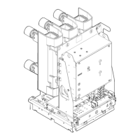
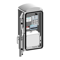
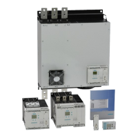
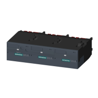
Fig. 33 to Fig. 39 show some non-binding examples of vacuum circuit-breaker mod-
ules.
The circuit diagrams for the vacuum circuit-breaker module are compiled depending
on your order.
Mechanical manual closing and electrical closing
Fig. 33 Sample circuit diagram – connection via low-voltage interface, 64-pole,
basic version
Electrical manual closing and electrical closing
Fig. 34 Example – circuit diagram with connection via low-voltage interface 64-
pole.
This legend is also valid for the following circuit diagrams.
HA Manual opening S3 Position switch (opens when closing spring is charged)
HE Manual closing S41, S42 Position switches (signal charging status)
K1 Contactor relay (anti-pumping device) S6, S7 Position switches (for circuit-breaker tripping signal)
M1 Motor X0 Low-voltage interface
P Energy storage mechanism Y1 1st shunt release
R1 Resistor Y2 2nd shunt release
S1 Auxiliary switch Y4, Y5, Y6 Transformer-operated release
S10, S11 Position switch (mechanical anti-pumping device) Y7 Undervoltage release
S12 Position switch (prevents electrical closing if there is a
mechanical locking device)
Y9 Closing solenoid
S21, S22 Position switches (switch off the motor after charging) V6 Integrated rectifiers for motor
 Loading...