© Siemens AG • 07/2003 11
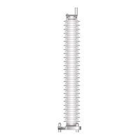
lower insulating sockets. The arrester must be placed and mounted with four bolts M10 × 50 on the
base plate by means of appropriate lifting gear (crane, tackle) comprising slings and lifting lugs [Fig. 7].
Fig. 10 Basic plate for isolated installation, 3 hole mounting Ø 200 … 276 mm 3× M12
Basic plate for isolated installation, 4 hole mounting 200 × 200 mm² 4× M16
Attention
Do not remove the insulating tube from the bolts M 16 x 130.
Put according to the drilling plan the four lower insulating sockets [2/Fig. 11] to the holes of the support
[1]. The base plate [3] and the upper insulating [4] sockets can be mounted with four bolts M16 × 130
on the lower insulating sockets. The arrester [5] must be placed and mounted with four bolts M10 × 50
on the base plate by means of appropriate lifting gear (crane, tackle) comprising slings and lifting lugs
[Fig. 7].
1 Support
2 Lower insulating socket
3 Base plate
4 upper insulating socket
5Arrester
Fig. 11 Basic plate for isolated installation, 4-hole mounting M16, 200×200 mm²
Basic plate for isolated installation, 4 hole mounting 310 × 310 mm² 4× M20 (standing installation)
Attention
Do not remove the insulating tube from the bolts M 20 x 110.
Put according to the drilling plan the four lower insulating sockets [2 [2/Fig. 12] to the holes of the sup-
port [1]. The base plate [3] and the upper insulating [4] sockets can be mounted with four bolts
M20 × 110 on the lower insulating sockets. The arrester [5] must be placed and mounted with four
bolts M10 × 50 on the base plate by means of appropriate lifting gear (crane, tackle) comprising slings
and lifting lugs [Fig. 7].