Do you have a question about the Siemens TPS3 and is the answer not in the manual?
General warning about death or serious injury from electrical hazards.
Risks associated with improper bonding and grounding of the SPD system.
Instructions against performing high-potential testing on installed SPDs.
Definition and qualifications required for personnel working with the SPD.
Warning against dielectric or high-potential testing on installed SPDs.
Information regarding the warranty coverage for Siemens AC Panel protection products.
Steps for inspecting the unit for damage upon receipt.
Recommendations for storing the SPD unit in a clean, dry environment.
Updates related to UL 1449 and NEC Article 285 affecting SPD terminology and testing.
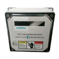
Explanation of SPD Type 1, 2, 3, and 4 classifications and their installation.
How SPDs function to protect equipment from overvoltages.
Importance of matching SPD voltage rating to the installed equipment.
Guidelines for proper equipment grounding conductor and single-point ground systems.
Warning about potential high line-to-ground voltages on ungrounded systems.
Operating temperature range, humidity, and negligible audible noise of the SPD.
Instructions for creating an opening for the display on P1 panelboards.
Procedure for adjusting phase labeling for the display PCB.
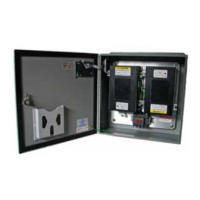
Detailed steps for mounting and connecting the TPS3 01 module in P1 panels.
Distinction in neutral connector wiring for S1/S2/SE panels compared to S3 panels.
Procedure for adjusting phase labeling for the display PCB.
Detailed steps for mounting and connecting the TPS3 01 module in S1/S2/SE panels.
Explanation of the W option's repositioned phase tabs for breaker connections.
Guidelines for selecting breaker size, conductors, and minimizing lead lengths.
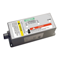
Instructions for replacing a TPS3 05 module in TPS3 05 units.
Instructions for replacing a TPS3 06 module in TPS3 06 units.
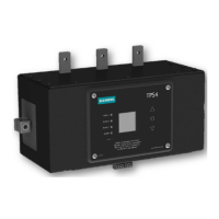
Procedure for custom factory installation of TPS3 modules in TIASTAR MCCs.
Guidelines for mounting the diagnostic display for visibility and protection.
Conditions for bench testing, including voltage, grounding, and enclosure security.
Overview of status LEDs, alarms, and touchpad controls on the display panel.
Functionality of the surge counter option for tracking voltage surge events.
Description of dry contacts for remote indication of SPD status.
Guidance on addressing bonding/grounding issues and sustained overvoltages.
How to interpret and respond to N-G voltage indicator alerts.
Steps for field-replaceable module service and disassembly restrictions.
Steps for field-replacing the display unit and ensuring weather resistance.
Guidance on periodic inspections using built-in diagnostics.
Policy on handling alarm conditions and replacing the entire SPD unit.
Information required when contacting Siemens TPS3 Technical Support.
| Brand | Siemens |
|---|---|
| Model | TPS3 |
| Category | Surge Protector |
| Language | English |