Table of Contents
Failure to Follow These Instructions Could Result in Death or Serious Injury ...................... 2
Do Not Hi-Pot Test SPDs .....................................................................................................................................................2
Introduction .......................................................................................................................... 1
Warning and Safety Information ........................................................................................................................................1
Qualified Person ................................................................................................................................................................1
Danger..............................................................................................................................................................................1
Warning ............................................................................................................................................................................1
Caution .............................................................................................................................................................................1
Do Not Hi-Pot Test SPDs .....................................................................................................................................................1
Limited Warranty ...............................................................................................................................................................1
Unpacking and Preliminary Inspection ...............................................................................................................................1
Storage .............................................................................................................................................................................2
Industry Standards Changes - 2009 ...................................................................................................................................2
Siemens TPS3 SPDs have the following Type designations ..................................................................................................2
Equipment Performance ....................................................................................................................................................2
Voltage Rating ..................................................................................................................................................................2
General Information .............................................................................................................. 4
Precautionary Statement Regarding SPDs on Ungrounded Systems ....................................................................................4
Overcurrent Protection ......................................................................................................................................................4
System Grounding.............................................................................................................................................................4
Environment .....................................................................................................................................................................4
Audible Noise ....................................................................................................................................................................4
Dead front modification Instruction Changes for P1 SPD Instructions ..................................................................................4
P1 Dead Front Knockout Plate Removal Instructions ...........................................................................................................4
TPS3 01 Installation Instructions for: Lighting Panelboards Type P1, P2, P3 ........................ 5
TPS3 01 Installation Instructions for: 400/600 amp S1/S2 and All SE Panels ........................... 6
UL 1283 required language concerning the installation of EMI Filters .................................................................................7
W option Suffix: ...............................................................................................................................................................7
TPS3 05 and TPS3 06 Module Replacement Instructions ..................................................... 8
TPS3 01 and TPS3 06 Module Installation Instructions: MCC ............................................... 9
Operation ............................................................................................................................ 10
TPS3 Control and Diagnostic Display Panel .......................................................................................................................10
Display Panel with Surge Counter Option .........................................................................................................................10
Dry Contacts Feature .......................................................................................................................................................10
Maintenance ....................................................................................................................... 11
Troubleshooting & Service ...............................................................................................................................................11
Abnormal N-G Voltage Indicators .....................................................................................................................................11
Module Replacement & Service .......................................................................................................................................11
Technical Support ...........................................................................................................................................................12
Display Replacement .......................................................................................................................................................12
Preventive Maintenance (Inspection and Testing) .............................................................................................................12
Corrective Maintenance (Repair) ......................................................................................................................................12
Tables
Table 1: TYPE DESIGNATIONS ............................................................................................................................................5
Table 2: MODEL NUMBER DECODER ..................................................................................................................................6
Table 3: CONTENTS FOR INSTALLATION IN Lighting Panelboards Type P1, P2, P3 ................................................................8
Table 4: CONTENTS for installation in 400/600 amp S1/S2 and All SE Panels .......................................................................9
Figures
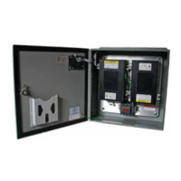
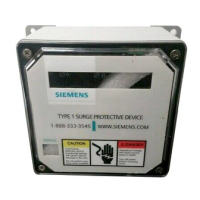
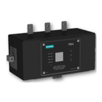
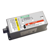
Figure 1: SPD Types ..........................................................................................................................................................2
Figure 2: Dead Front Modification Instruction ...................................................................................................................4
Figure 3: 250 AMP Max P1 Panels .....................................................................................................................................5
Figure 4: 400/600 AMP S1/S2 AND ALL SE PANELS - TPS3 01 Unit with the NK Accessory Kit ..............................................6
Figure 5: P4, P5 AND Front Connected Distribution Switchboards ......................................................................................8
Figure 6: Service Section Switchboards and low voltage Switchgear ..................................................................................8
Figure 7: Installation in a MCC ..........................................................................................................................................9
Figure 8: BASIC DISPLAY - HORIZONTAL ..........................................................................................................................10
Figure 9: BASIC DISPLAY - VERTICAL ...............................................................................................................................10
Figure 10: DRY CONTACT PIN CONFIGURATION ................................................................................................................10
3