Do you have a question about the Siemens TPS3 12 and is the answer not in the manual?
Critical safety warning regarding severe shock hazards and potential for death or serious injury.
Hazards associated with improper bonding and grounding, potentially causing high voltages and SPD failure.
Explicitly prohibits high-potential testing of the SPD unit to prevent damage.
Provides detailed safety warnings, hazard level definitions, and general safety precautions.
Defines the qualifications required for personnel installing or servicing the equipment.
Discusses changes to industry standards like UL 1449 and NEC affecting SPD definitions and testing.
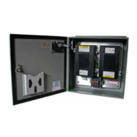
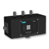
Describes the TPS3 12 and TPS3 15 product lines, including single and dual module configurations.
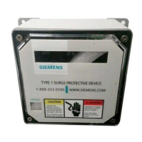
Explains Type 1, 2, 3, and 4 SPD classifications based on installation location and function.
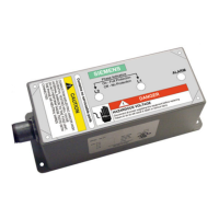
Details the device's internal overcurrent and overtemperature protection mechanisms.
Explains how SPDs redirect surge energy to earth ground during overvoltage events.
Details acceptable ambient temperature, humidity, and enclosure requirements for SPD installation.
Discusses the implications and requirements for installing SPDs on the line side versus the load side of the service disconnect.
Provides information on physical aspects of the SPD, including mounting options and weight.
Emphasizes the importance of short, straight leads for maximizing SPD performance and minimizing voltage drops.
Details the requirements for proper equipment grounding conductor and system grounding for optimal SPD performance.
Specifies recommended wire sizes and torque values for SPD connections to ensure safe and effective installation.
Provides guidance on considerations and methods for flush mounting the SPD unit.
Explains the functionality and installation requirements for the optional disconnect switch.
Outlines essential pre-installation steps including code compliance, mounting, wiring, and system checks.
Details how to mount the SPD module and connect conductors, emphasizing short leads and proper labeling.
Stresses the importance of proper system grounding (N-G bonding) and checking for faults before energizing the SPD.
Describes the function of LEDs and controls on the diagnostic panel for monitoring SPD status and alarms.
Explains how the surge counter registers overvoltage events and how to reset it.
Details the use of dry contacts for remote monitoring of SPD status and inoperative conditions.
Provides guidance on troubleshooting common SPD issues, emphasizing bonding and grounding problems.
Outlines the procedure for safely replacing field-replaceable SPD modules.
Explains the process for replacing the diagnostic display unit, including gasket replacement.
| Response Time | ≤ 25 ns |
|---|---|
| Standards | IEC 61643-11, EN 61643-11 |
| Voltage Protection Rating (VPR) | 1.5 kV |
| Voltage Protection Level (Up) | 1.5 kV |
| Operating Temperature Range | -40°C to +80°C |
| Mounting | DIN rail |