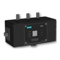
TPS SERIES DESCRIPTION
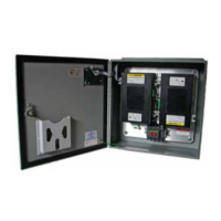
TPS3 12 Externally mounted SPD, single module in enclosure, standard modes of protection
TPS3 L12 Externally mounted SPD, single module in enclosure, 10 modes of protection
TPS3 15 Externally mounted SPD, dual replaceable modules in enclosure, standard modes of protection
TPS3 L15 Externally mounted SPD, dual replaceable modules in enclosure, 10 modes of protection
Table 1: Model Number Decoder
AVAILABLE VOLTAGES
VOLTAGE CODES TPS3 12 TPS3 L12 TPS3 15 TPS3 L15
A = 240/120V Split Phase 1Ø, 3W Plus Grnd (Fig 1)
√ √ √ √
B = 240/120V 3Ø, High Leg Delta (B High) (Fig 3)
√ √ √ √
C = 208Y/120V 3Ø, 4W Plus Grnd (Fig 2)
√ √ √ √
D = 240V 3Ø, 3W Plus Grnd (Fig4)
√ √
E = 480Y/277V 3Ø, 4W Plus Grnd (Fig 2)
√ √ √ √
F = 480V 3Ø, 3W Plus Grnd (Fig 4)
√ √
G = 600V 3Ø, 3W Plus Grnd (Fig 4)
√ √
K = 380Y/220V 3Ø, 4W Plus Grnd (Fig 2)
√ √ √ √
L = 600Y/347V 3Ø, 4W Plus Grnd (Fig 2)
√ √
S = 400Y/230V 3Ø, 4W Plus Grnd (Fig 2)
√ √ √ √
AVALABLE SURGE CURRENT RATING
SURGE CURRENT RATING TPS3 12 TPS3 L12 TPS3 15 TPS3 L15
10 = 100kA per phase
√
15 = 150kA per phase
√ √ √
20 = 200kA per phase
√
25 = 250kA per phase
√
30 = 300kA per phase
√ √ √
40 = 400kA per phase
√
45 = 450kA per phase
√
50 = 500kA per phase
√
60 = 600kA per phase
√ √
80 = 800kA per phase
√
90 = 900kA per phase
√
1K = 1000kA per phase
√
AVAILABLE OPTIONS (When Option is Not Selected Include a "0" in the Field)
OPTION CODE / DESCRIPTION TPS3 12 TPS3 L12 TPS3 15 TPS3 L15
0 = Standard NEMA 1/12/3R/04 enclosure
√ √ √ √
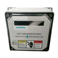
V = NEMA 4X Non-metallic enclosure
√ √ √ √
S = NEMA 4X Stainless Steel enclosure
√ √ √ √
F = NEMA 1 Flush Mount enclosure
√ √ √ √
P = NEAM 1 Screwcover Pullbox enclosure
√ √ √ √
X = Surge Counter
√ √ √ √
D = Internal Rotary Disconnect Switch
√ √
T = Thru-door Rotary Disconnect Switch
√ √ √ √
Figure 1
SPLIT
2 Hots, 1 Neu, 1 Grnd
Hot (BLK)
Hot (BLK)
Neutral (WHT)
V
V
}
}
Ground (GRN)
Figure 2
WYE
3 Hots, 1 Neu, 1 Grnd
}
Phase A (BLK)
Phase B (BLK)
Neutral (WHT)
Phase C (BLK)
Ground (GRN)
A
C
N
V
B
Figure 3
HI-LEG DELTA (B High)
3 Hots, (B HIGH),
1 Neu, 1 Grnd
Phase A (BLK)
Phase B (ORNG)
Neutral (WHT)
Phase C (BLK)
Ground (GRN)
}
V
Figure 4
DELTA & HRG WYE
3 Hots, 1 Grnd
Phase A (BLK)
Phase C (BLK)
Phase B (BLK)
Ground (GRN)
}
V
3